Corrosion-resistant member and process of producing the same

a technology of corrosion resistance and corrosion resistance, which is applied in the direction of metallic material coating process, water-setting substance layered product, electrical equipment, etc., can solve the problems of large apparatus scale, low large generation of particles, so as to improve the corrosion resistance of the same, the effect of good bonding of particles and less particle generation

Inactive Publication Date: 2009-02-26
TOSOH CORP
View PDF3 Cites 0 Cited by
  • Summary
  • Abstract
  • Description
  • Claims
  • Application Information

AI Technical Summary

Benefits of technology

[0010]Accordingly, one object of the present invention is to provide a corrosion-resistant member comprising a base material having formed thereon a vitreous sprayed coating which has high corrosion resistance, causes less generation of particles, can easily be produced, and contains nitrogen.
[0012]As a result of extensive investigations in view of the above circumstances, it has been found that a material comprising Si, O, N, Group 2a element, and at least one element selected from the group consisting of Al, B, Zr and Ti is suitable for spraying, a dense sprayed coating having good bonding of particles with each other can be formed by spraying the material to a base material, and as a result, corrosion resistance of a member is markedly improved, and generation of particles is less.
[0013]It has further been found that a material comprising Si, O, N, Group 3a element, and at least one element selected from the group consisting of B, Zr and Ti is also suitable for spraying, and a dense sprayed coating having good bonding of particles with each other can be formed by spraying the material to a base material, and as a result, corrosion resistance of a member is markedly improved, and generation of particles is less.

Problems solved by technology

However, these members involved problems such that the member wastes away in a short period of time, and the member causes the generation of particles in the device.
However, to produce such corrosion-resistant glasses, reducing atmosphere or inert atmosphere is required, resulting in a large scale of apparatus, and as a result, the corrosion-resistant member tends to be expensive.
Further, such a composition is not always sufficient in corrosion resistance.
However, according to the conventional spraying technologies, the formation of a dense sprayed coating containing nitrogen has been difficult, and metals or oxide ceramics have mainly be used in the conventional formation of a protective film by spraying.
However, since those sprayed coatings have high melting point, the sprayed powder which is not sufficiently melted deposits on a base material.
As a result, bonding of mutual particles of the sprayed coating is weak, and the number of pores increases, resulting in decrease of density.
Consequently, corrosion selectively proceeds at the grain boundary or in pores of the member in plasma etching, whereby particles tend to generate due to dropout of crystal particles.
Further, durability of the sprayed coating to corrosive gases or plasma has not been sufficient.
In addition, an apparatus used in explosion spraying is expensive, deposition efficiency of the sprayed coating is poor, and a metal base material such as aluminum may deform by wind pressure at explosion.
As described above, in the step of using corrosive gases or plasma in a semiconductor production process, there have been the problems of particle generation due to corrosion of a member, contamination of a product due to such generation, gain decrease, and the like.
There has been further problem of decrease in life of a member due to low corrosion resistance of the member.
However, such a member has not always sufficient in corrosion resistance.

Method used


Image

  • Corrosion-resistant member and process of producing the same
  • Corrosion-resistant member and process of producing the same

Examples


first embodiment

[0024]The first embodiment of the present invention is to provide a corrosion-resistant member comprising a base material having formed thereon a sprayed coating, the sprayed coating being formed on the site of the base material to exposed to corrosive gases or plasma and comprising Si, O, N, Group 2a element, and at least one element selected from the group consisting of Al, B, Zr and Ti.

[0025]The Group 2a element used herein means Group 2a element in the Periodic Table, and specifically means Be, Mg; Ca, Sr and Ba. The sprayed coating constituting the corrosion-resistant member of the present invention comprises glass as the main component. Therefore, the sprayed coating has low reactivity with corrosive gases or its plasma. Even if the sprayed coating is reacted with fluorine in the corrosive gas, the resulting product is a high boiling compound which is difficult to be etched by plasma. Thus, the sprayed coating has the effect to suppress etching with plasma or corrosive gases. ...

second embodiment

[0035]The second embodiment of the present invention is to provide a corrosion-resistant member comprising a base material having formed thereon a sprayed coating, the sprayed coating being formed on the site of the base material to exposed to corrosive gases or plasma and comprising Si, O, N, Group 3a element, and at least one element selected from the group consisting of B, Zr and Ti.

[0036]The Group 3a element used herein means Group 3a element in the Periodic Table, and specifically means Sc, Y and lanthanoid element. The material containing Group 3a element, Zr and Ti has low reactivity with corrosive gases or its plasma. Even if the sprayed coating is reacted with fluorine in the corrosive gas, the resulting product is a high boiling compound. Thus, the sprayed coating has the effect to suppress etching with plasma or corrosive gases.

[0037]Regarding the concentration of each component in the corrosion-resistant member in the second embodiment, when Zr and / or Ti are used, it is ...

third embodiment

[0043]The production process of the corrosion-resistant member according to the first and second embodiments is described below as the third embodiment.

[0044]The corrosion-resistant member can be produced by forming a corrosion-resistant sprayed coating on a base material by spraying.

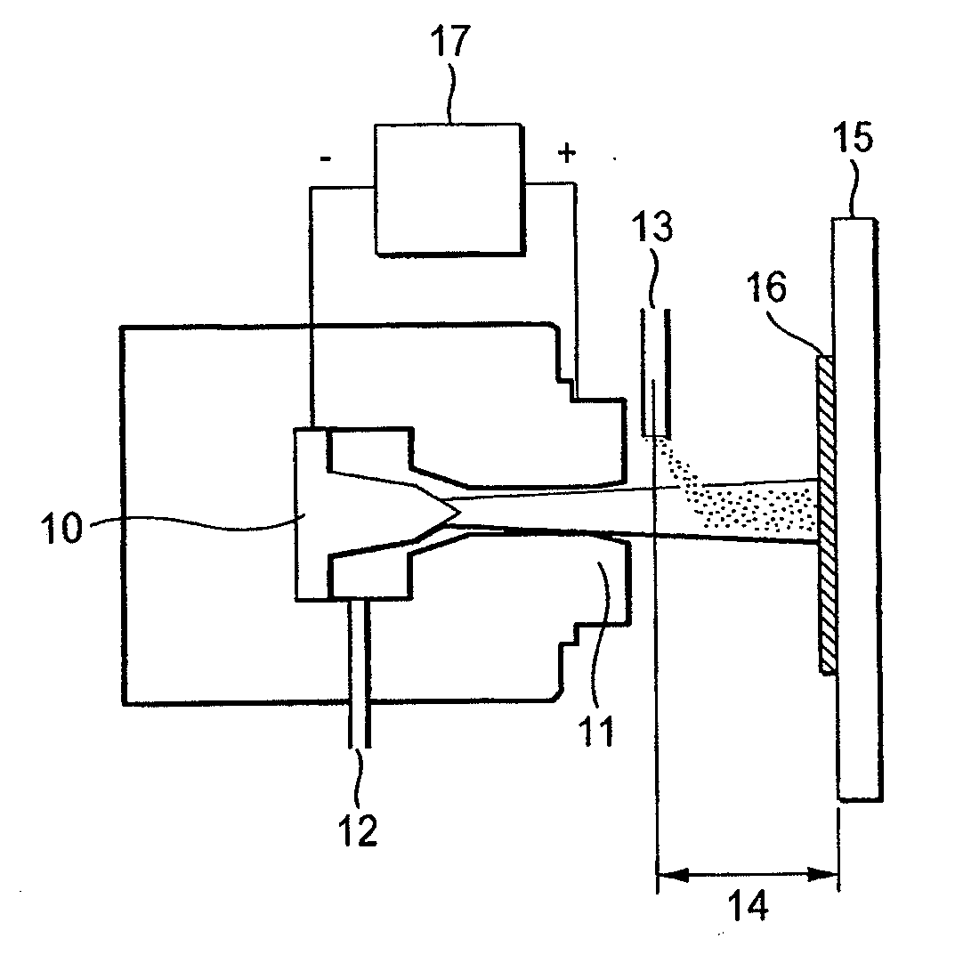
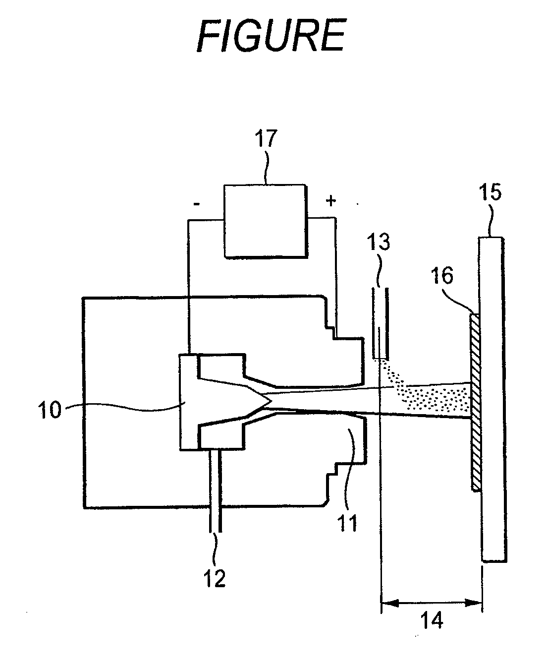
[0045]The spraying method used is preferably a plasma spray. The FIGURE shows a general plasma spraying device. The plasma spraying device functions as follows. Plasma gas 12 flown between an anode 11 and a cathode 12 causes arc discharge to form a plasma jet. The plasma jet is used as a heat source to melt a spraying powder 13. The molten spraying powder strikes a base material 15 and deposits thereon.

[0046]The plasma spraying device can use an inert gas such as N2 or Ar, reducing gas such as H2, or a mixed gas of those, as a plasma gas. Where a nitrogen-containing substance is sprayed, if a plasma gas contains oxygen, decomposition occurs during spraying, and nitrogen disappears from the sprayed coati...


PUM

PropertyMeasurementUnit
poweraaaaaaaaaa
distanceaaaaaaaaaa
particle diameteraaaaaaaaaa

Abstract

A corrosion-resistant member comprising a base material having formed thereon a spayed coating having high corrosion resistance to corrosive gases or plasma, and a process of producing the same are disclosed. The corrosion-resistant member comprises a base material having formed thereon a sprayed coating, the sprayed coating being formed on the site of the base material to be exposed to corrosive gases or plasma and comprising Si, O, N, Group 2a element, and at least one element selected from the group consisting of Al, B, Zr and Ti, or comprises a base material having formed thereon a sprayed coating, the sprayed coating being formed on the site of the base material to be exposed to corrosive gases or plasma and comprising Si, O, N, Group 3a element, and at least one element selected from the group consisting of B, Zr and Ti.

Description

FIELD OF THE INVENTION[0001]The present invention relates to a member to be used in CVD (Chemical Vapor Deposition) devices, plasma treatment devices (plasma etching devices) and the like in manufacturing semiconductors, and a process of producing the same. In particular, the present invention relates to a corrosion-resistant member comprising a base material having formed thereon a spayed coating having high corrosion resistance to corrosive gases or plasma, and a process of producing the same.BACKGROUND ART[0002]Corrosive gases are frequently used for plasma etching in the manufacturing step of semiconductors, etc., and cleaning application of CVD devices. For these corrosive gases, fluorine based or chorine based gases, and the like are used. As the fluorine based gases, CF4, C2F6, C3Fs, CHF3 / CF4, SF6, and the like are used, and for the Cl based gases, Cl2, BCl3, CCl4, and the like are used. Further, it is also proposed to use HF, F2, or NF3.[0003]In portions coming into contact ...

Claims


Application Information

Patent Timeline
Patent Type & Authority Applications(United States)
IPC IPC(8): B32B17/06C23C4/06B32B18/00C23C4/10C23C4/12
CPCC23C4/10C23C4/12C23C4/127C04B35/58028C04B35/583C04B35/597C04B2235/5436C04B2235/3206C04B2235/3225C04B2235/3232C04B2235/3244C04B2235/386C04B2235/3873C04B35/62695C23C4/134H01L21/205
Inventor ABE, MASANORITAKAHASHI, KOYATA
Owner TOSOH CORP
Why Eureka
Try Eureka