Eureka AIR delivers breakthrough ideas for toughest innovation challenges, trusted by R&D personnel around the world.

Surface properties of polymeric materials with nanoscale functional coating

Inactive Publication Date: 2009-03-12
YOKLEY EDWARD MAXWELL +1
View PDF34 Cites 67 Cited by
  • Summary
  • Abstract
  • Description
  • Claims
  • Application Information

AI Technical Summary

Benefits of technology

[0014]Still another embodiment is a method of manufacturing a polymeric object. The method comprises providing a polymeric substrate, and exposing said substrate to a first stage that includes an initial plasma reactant so as to reduce a water contact angle of a surface of the substrate, and, wherein

Problems solved by technology

Traditional coating techniques such as spraying, painting, dip- or spin coating have proved difficult and unreliable due both to the properties of the coatings, and the typically low surface energy of the substrates.
However, these devices have long been known to cause injury, damage and discomfort to patients.
The origins of the damage and discomfort problems stem from adhesion to tissues and tearing during insertion and removal, and inflammation and infection development during implantation.
Adhesion failure of the coatings is a typical failure mode and results in the de-bonding of relatively large sections of the coatings on the cellular scale, leading to irritation, inflammation, pain, and a variety of local tissue responses that range from benign to life threatening to the patient.
The wide use of polymeric objects for skin and tissue contact applications has been limited by several confounding requirements.
In general the materials that meet these requirements have low surface energy and tend to be hydrophobic.
In the cases where natural polymers, such as latex rubbers are used in the construction of the object or device, there is the further complication of sensitivity to the natural rubber proteins and the materials used in the vulcanization of the natural latex.
The origins of the damage and discomfort problems stem from adhesion to tissues and tearing during insertion and removal, and inflammation and infection development during implantation.
These coatings are an improvement, but they generally suffer from poor adhesive bonding to the underlying surface.
The device materials of choice are inherently non reactive to reduce the incidence of reactions with the surrounding tissues, and as a result tend to be materials with low surface energy and poor moisture interaction.
This method and the products produced by it are inherently inferior to what is theoretically possible.
Specifically, the films tend to adhere poorly; they tend to be defective allowing small molecules and microbes to permeate them.
Also the film tends to be non-uniform due to agglomeration of the polymers in solution.
In some cases, the substrate swells and deforms over time.
The dip coating route also limits the kinds of molecules that can be put on the devices to solvent soluble species, which exclude most inorganic materials.
The solvent based coatings also require capital intensive solvent removal and drying steps on devices made of multiple materials with irregular shapes.
Previous methods to achieve such surface coatings are deficient in their delamination performance and are both capital intensive and difficult to apply.
There are capital requirements for solvent removal, and process control issues for urethane type reactive coating processes when implemented on large scale.
Further, there are difficulties in the subsequent sterilization of the devices, since some of the coating chemistries are not compatible with autoclaving, Ethylene Oxide sterilization, or photochemical / radiation methods.
Traditional coating techniques have proved difficult to apply due both to the properties of the coatings, and the typically low surface energy of the preferred substrates.
In addition, these polymers have low melt temperatures that are incompatible with high temperature coating processes.

Method used


Image

  • Surface properties of polymeric materials with nanoscale functional coating
  • Surface properties of polymeric materials with nanoscale functional coating
  • Surface properties of polymeric materials with nanoscale functional coating

Examples


Embodiment Construction

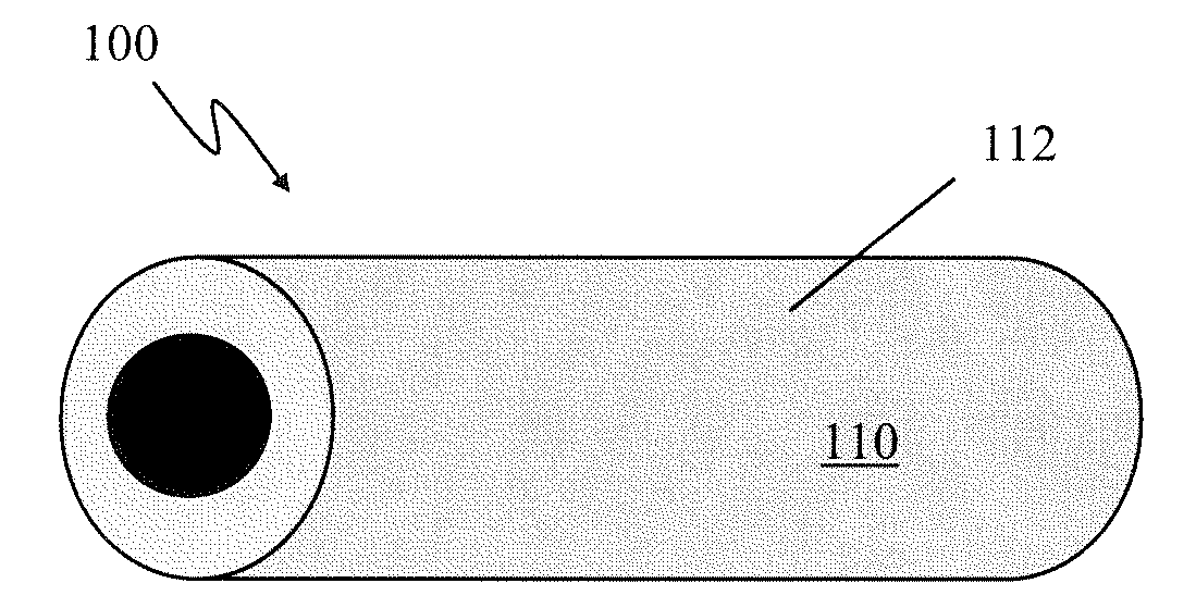
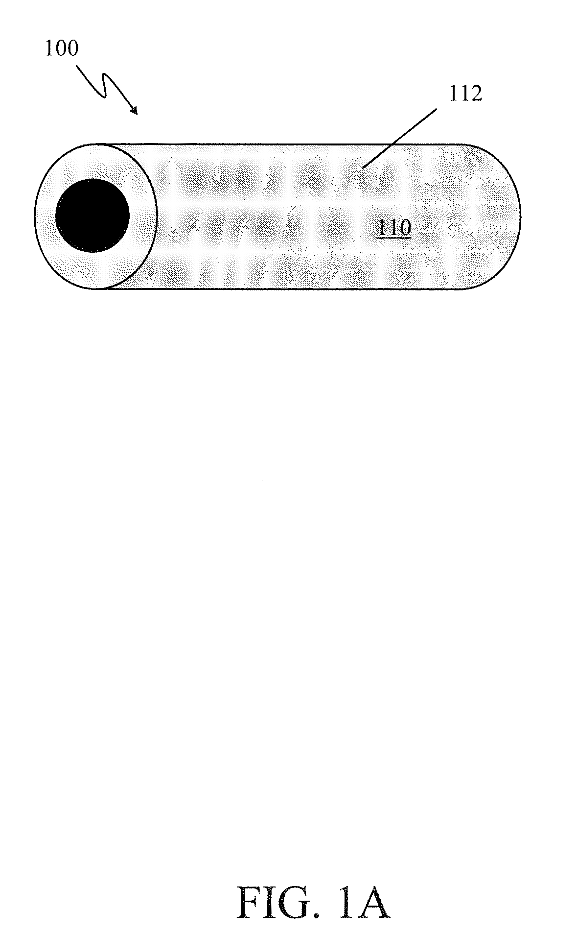
[0017]FIGS. 1A-1C presents perspective views of an example polymeric object 100 of the present invention at different stages of fabrication. The example embodiment presented is an implantable polymeric object 100 such as a catheter. As shown in FIG. 1A the object 100 is made by a process that comprises providing a polymeric substrate 110 having a surface 112.

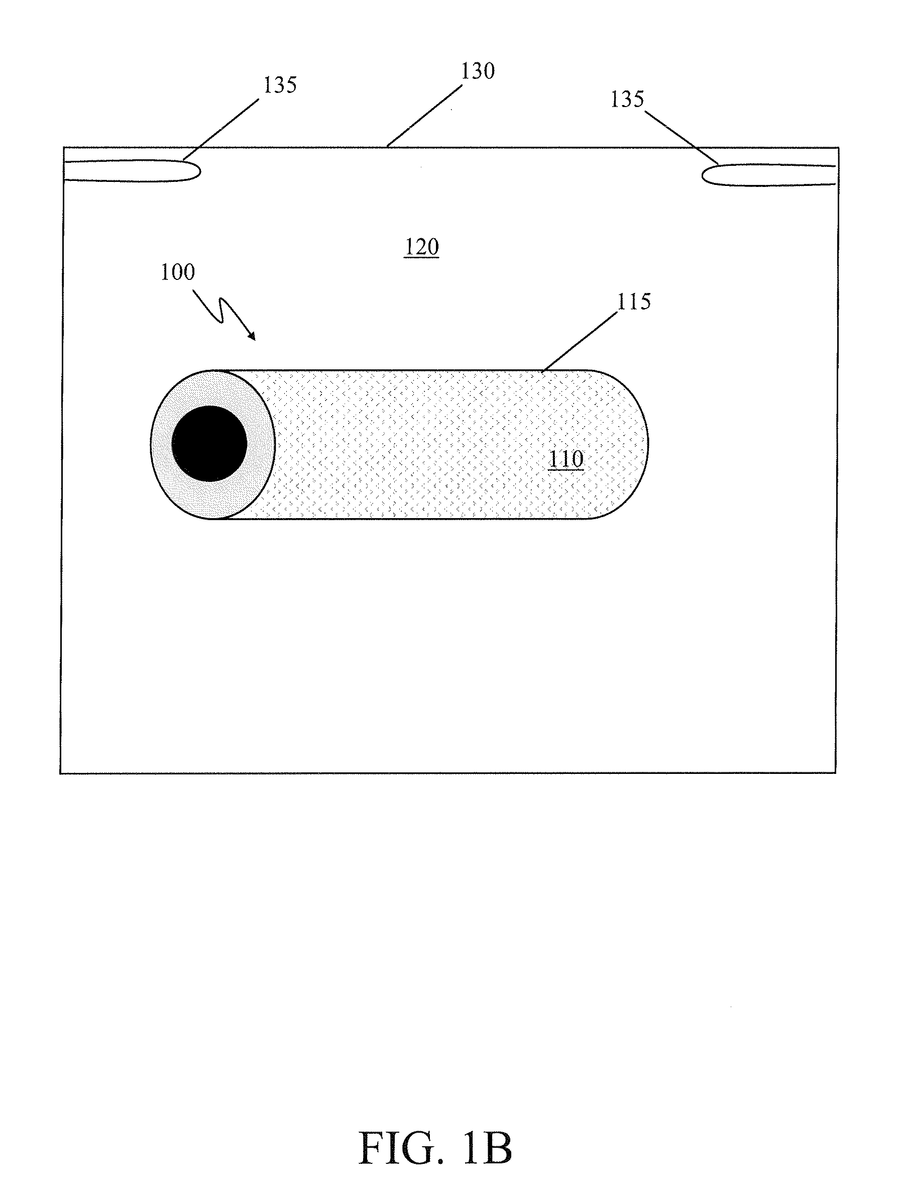
[0018]FIG. 1B shows the object 100 while exposing the substrate 110 to an initial plasma reactant 120. The initial plasma treatment activates the substrate's surface 112 (FIG. 1A) to a grafting reaction. Such activation can be verified by measuring a reduction in a water contact angle of a surface 115 of the substrate 110 as compared to the surface 112 before the initial plasma treatment. As shown in FIG. 1B, the initial plasma treatment is carried out in a plasma chamber 130 having electrodes 135. The electrodes 135 are maintained in a range from about 10° C. to about 100° C. during the initial plasma treatment.

[0019]FIG. 1C sh...


PUM

PropertyMeasurementUnit
Temperatureaaaaaaaaaa
Pressureaaaaaaaaaa

Abstract

A method of manufacturing a polymeric object that comprises providing a polymeric substrate, and exposing said substrate to a first stage that includes an initial plasma reactant so as to reduce a water contact angle of a surface of the substrate, and, wherein the initial plasma treatment activates the surface to a grafting reaction, The method further includes exposing the activated substrate surface to a second stage that includes a second plasma reactant to thereby deposit a grafted material on the activated substrate surface to form a grafted surface.

Description

CROSS-REFERENCE TO RELATED APPLICATION[0001]This Application claims the benefit of U.S. Provisional Application Ser. No. 60 / 970,582 filed on Sep. 7, 2007, entitled “IMPROVING SURFACE PROPERTIES OF POLYMERIC MATERIALS WITH NANOSCALE FUNCTIONAL COATING,” commonly assigned with the present invention and incorporated herein by reference.TECHNICAL FIELD OF THE INVENTION[0002]The invention is directed, in general, polymeric objects and more particularly, to surface modification of objects, and methods of manufacturing thereof.BACKGROUND OF THE INVENTION[0003]There is a need for engineering the air-polymer interface for specific applications. For example, it is often desirous modify the surface without altering the bulk properties of substrates and nanoscale coatings have the potential to greatly enhance the structural and functional performance of fabricated polymeric devices. Enhancement of the surface can occur with designed organic, inorganic or hybrid polymeric coatings. Traditional c...

Claims


Application Information

Patent Timeline
IPC IPC(8): A61M25/00B05D3/06B32B27/36B32B27/32
CPCA61L29/14A61L31/14A61L2400/18A61M25/0009A61M25/0017A61M25/0045Y10T428/2967B05D3/144B29C59/142D06M10/025D06M10/04D06M14/28B05D1/62Y10T428/31935Y10T428/31938
Inventor YOKLEY, EDWARD MAXWELLOBENG, YAW SAMUEL
Owner YOKLEY EDWARD MAXWELL
Why Eureka
Eureka Blog
Learn More