Apparatus and method for raman spectroscopy and microscopy with time domain spectral analysis

a technology of raman spectroscopy and microscopy, applied in the field of vibrational spectroscopy, can solve the problems of not being able to repeat the reaction or measur

Inactive Publication Date: 2009-03-19
RGT UNIV OF CALIFORNIA
View PDF13 Cites 50 Cited by
  • Summary
  • Abstract
  • Description
  • Claims
  • Application Information

AI Technical Summary

Benefits of technology

[0020]The present invention is an apparatus and method of measuring stimulated Raman scattering (SRS), coherent anti-Stokes Raman scattering (CARS), coherent Stokes Raman scattering (CSRS), and other Raman-type spectra of atomic, molecular, and crystalline species. The method utilizes dispersion to convert an optical spectrum into a waveform which can be detected directly in the time domain without the use of a conventional spectrometer. In the case of stimulated Raman spectroscopy, for example, the method exposes a sample to a pulsed

Problems solved by technology

In these situations, it may not be possible to run the reaction repetitively or measure the spectra of the molecules at any one momen

Method used


Image

  • Apparatus and method for raman spectroscopy and microscopy with time domain spectral analysis
  • Apparatus and method for raman spectroscopy and microscopy with time domain spectral analysis
  • Apparatus and method for raman spectroscopy and microscopy with time domain spectral analysis

Examples


example 1

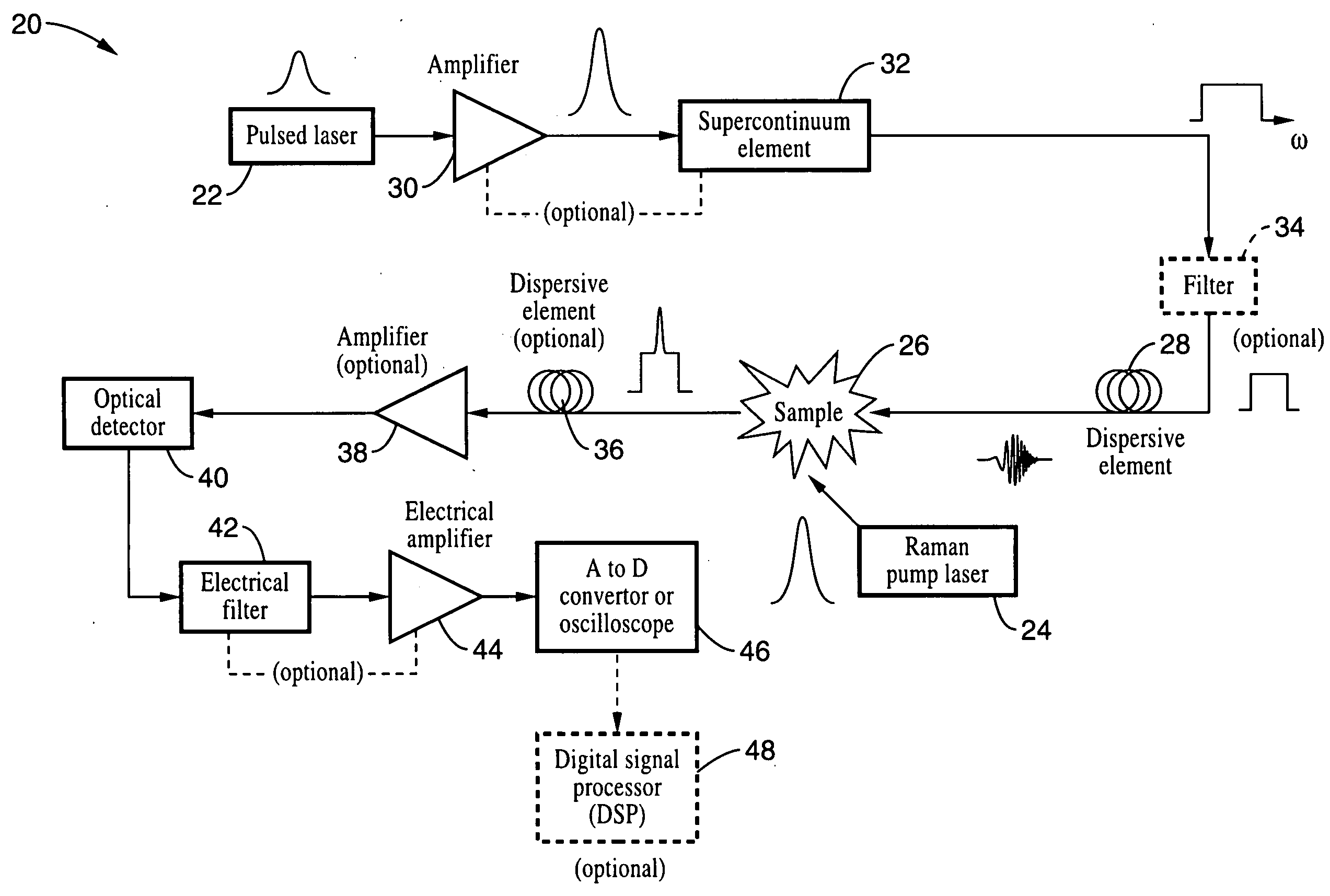
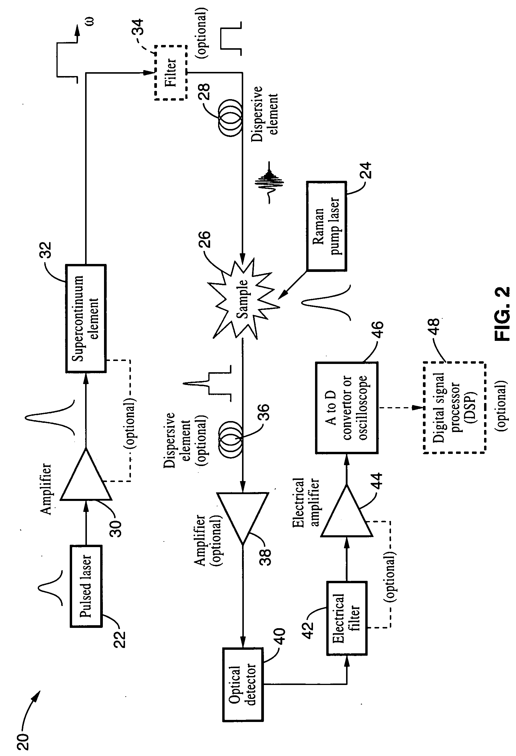
[0085]To illustrate the invention, the embodiment shown schematically in FIG. 2 was constructed using a silicon waveguide as a sample. Silicon was selected because the vibrational Raman spectrum of silicon has been well studied using standard techniques and stimulated Raman scattering in silicon has been employed to construct Raman lasers and amplifiers.

[0086]The master oscillator that was used to generate the pump and probe pulses was a mode-locked erbium-doped fiber laser producing near-transform-limited picosecond pulses at approximately 1550 nm with a repetition rate of 25 MHz. The pump pulses were generated by pre-stretching a fraction of the output pulses to approximately 50 ps and then amplifying in a large-mode-area erbium-doped fiber amplifier to a desired level.

[0087]A supercontinuum Stokes probe was generated directly within the gain fiber of a separate specialty erbium-doped fiber amplifier using a portion of the oscillator output as the seed. The supercontinuum pulses w...

example 2

[0092]In order to demonstrate the utility of Raman-post amplification for the present invention and other spectroscopic signals, apparatus was used to amplify weak spectroscopic signals. The detection of weak signals presents a significant challenge in many spectroscopic measurements. This issue is especially important in single-shot applications since it is not possible to use averaging to reduce noise. For example, the use of dispersion to chirp the signal typically weakens the signal because dispersive elements usually have significant loss. Optical amplification of the signal may be necessary to resolve this problem.

[0093]Unfortunately, traditional optical amplifiers are generally only available for a limited number of restricted wavelength bands. On the other hand, Raman amplifiers are not fundamentally tethered to specific wavelengths, but can operate wherever suitable continuous-wave Raman pumps and gain media are available. Distributed Raman amplification is particularly use...


PUM


Abstract

An apparatus and method for measuring Raman-type spectra using optical dispersion to convert an optical spectrum into a waveform which can be detected directly in the time domain without the use of a conventional spectrometer. In the example of stimulated Raman spectroscopy, the apparatus and method exposes a sample to a chirped, pulsed probe beam and a Raman pump beam and the resulting Raman spectra is detected by an optical detector in the time domain, and analyzed. Alternatively, the Raman spectra from the probe and pump beams is chirped with a dispersive element prior to detection and analysis. Each probe pulse provides a snapshot of the Raman spectrum that is sampled in time so that neither repetitive waveforms nor static samples are required. Therefore, high speed acquisitions and high throughput assays can be conducted. To facilitate detection, these spectral signals can also be amplified using distributed Raman amplification directly in the dispersive element.

Description

CROSS-REFERENCE TO RELATED APPLICATIONS[0001]This application claims priority from, and is a 35 U.S.C. § 111 (a) continuation of, co-pending PCT international application serial number PCT / US2007 / 065393, filed on Mar. 28, 2007, incorporated herein by reference in its entirety, which claims priority from U.S. provisional application Ser. No. 60 / 787,129 filed on Mar. 28, 2006, incorporated herein by reference in its entirety.STATEMENT REGARDING FEDERALLY SPONSORED RESEARCH OR DEVELOPMENT[0002]Not ApplicableINCORPORATION-BY-REFERENCE OF MATERIAL SUBMITTED ON A COMPACT DISC[0003]Not ApplicableBACKGROUND OF THE INVENTION[0004]1. Field of the Invention[0005]This invention pertains generally to vibrational spectroscopy, and more particularly to an apparatus and method for Raman spectroscopy including sample exposure to a chirped, pulsed probe beam and a Raman pump beam wherein temporal dispersion is employed to transform the Raman-scattered light into a time-domain waveform which is electr...

Claims


Application Information

Patent Timeline
IPC IPC(8): G01J3/44
CPCG01J3/10G01J3/4412G01J3/457G01N2021/655G01N21/65G01N21/658G01N2021/653G01N21/636
Inventor JALALI, BAHRAMSOLLI, DANIELCHOU, JASON
Owner RGT UNIV OF CALIFORNIA
Why Eureka
Try Eureka