
Processes for Producing Synthetic Pyrite

a technology of synthetic pyrite and pyrite, which is applied in the direction of non-aqueous electrolyte cells, cell components, oxygen/ozone/oxide/hydroxide, etc., can solve the problems of sacrificing the capacity of low power and low rate discharge, reducing the input of cell active materials in order to maximize high power performance, and reducing the effect of cell active material inputs

Active Publication Date: 2009-04-02
ENERGIZER BRANDS
View PDF16 Cites 16 Cited by
  • Summary
  • Abstract
  • Description
  • Claims
  • Application Information

AI Technical Summary

Benefits of technology

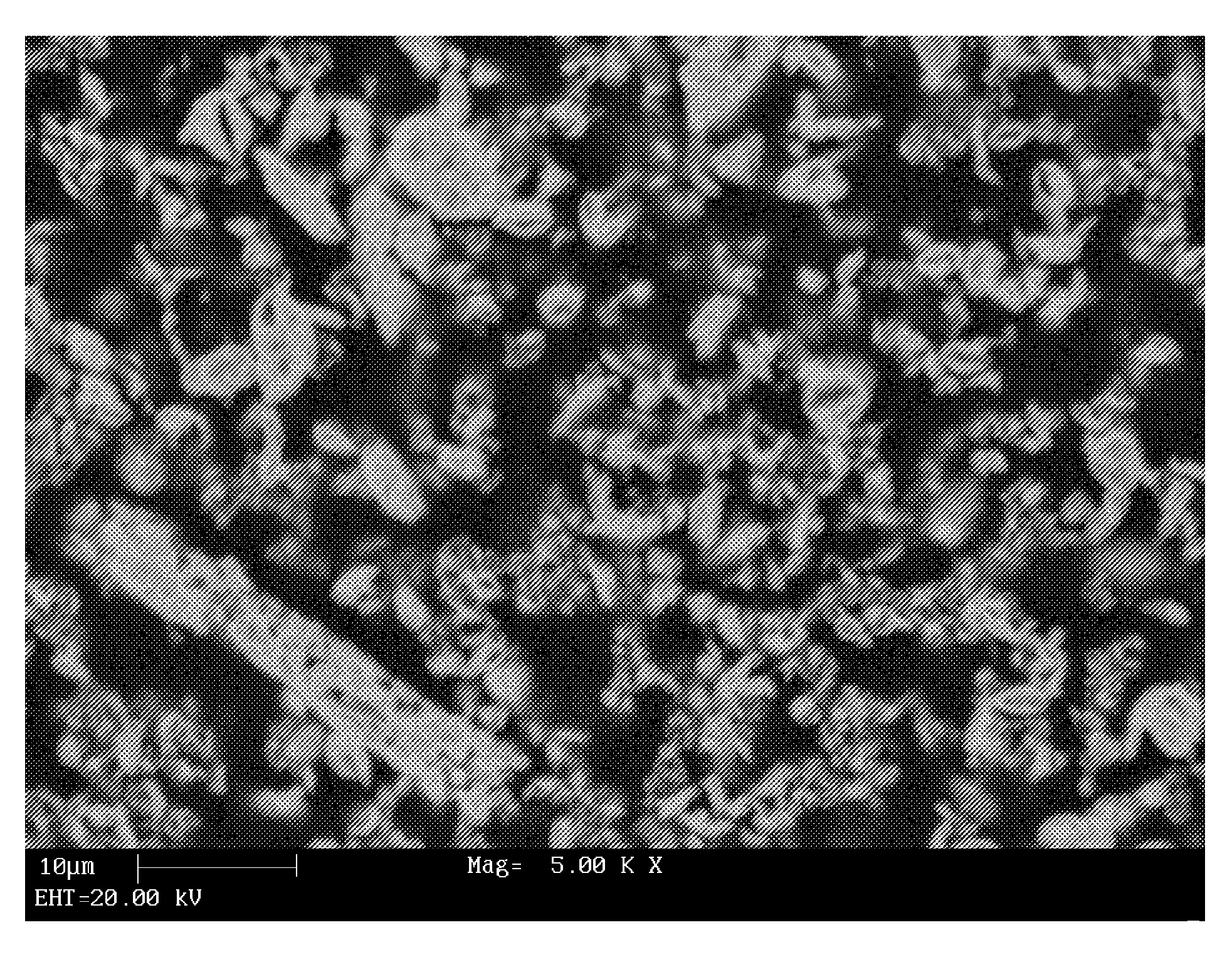
[0017]The processes may provide synthetic FeS2 particles ranging in size from a few microns down to tens of nanometers and can provide FeS2 having a relatively large surface area.

Problems solved by technology

However, there are practical limitations on the maximum internal volume.
This often means using designs containing less active materials, thus sacrificing capacity on low power and low rate discharge.
Reducing cell active material inputs in order to maximize high power performance is less desirable for batteries that are intended for both high and low power use than for batteries intended for only high power use.
There are, however, practical limitations to doing so.
However, changes made to increase strength can also adversely affect separator performance based on factors such as, for example, cell chemistry, electrode design and features, cell manufacturing process, intended cell use, anticipated storage and use conditions, etc.
For certain cell chemistries, maximizing the amounts of active materials in the cell can be more difficult.
These forces can cause bulging of the cell housing and short circuits through the separator.
Using thicker materials, however, further limits the internal volume available for active materials in cells with such active materials compared to cells with lower volume reaction products.
However, adding other active materials to the cathode mixture can affect the electrical and discharge characteristics of the cell.
As is clear from the above discussion, changes made to improve resistance to internal short circuits can be counterproductive in maximizing discharge capacity.
The fineness of the grind is limited by the reactivity of the particles with air and moisture.
As the particle size is reduced, the surface area thereof is increased and is more susceptible to weathering.
Small pyrite particles can generate sufficient heat during oxidation to cause hazardous fires within the processing operation.
Thus, during the storage period, the above-noted oxidation and weathering occur and the material degrades.
Moreover, the large iron disulfide particle sizes can impact processes such as calendering, causing substrate distortion, coating to substrate bond disruption, as well as failures from separator damage.
Impurities are believed to decrease inputs and contribute to problems such as internal shorting and other defects in batteries.

Method used


Image

  • Processes for Producing Synthetic Pyrite
  • Processes for Producing Synthetic Pyrite
  • Processes for Producing Synthetic Pyrite

Examples


example 1

Sulfidation Process

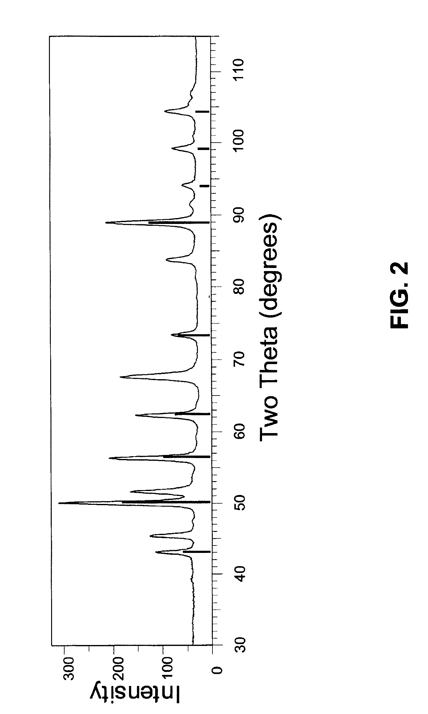
[0140]Synthetic FeS2 is prepared using a sulfidation process in accordance with the present invention as follows: 2.6 grams of nanorust (nano particles of Fe2O3) from Alfa Aesar having an average particle size of about 3 nm and 0.5 grams of elemental sulfur from Alfa Aesar having a particle size of about 1-2 μm are charged to a flask as part of a Labconco rotary evaporator. The system is purged with argon before the introduction of H2S is started. The flask is heated to the desired temperature using an oil bath. Hydrogen sulfide gas (about 6% volume percent in N2) is flowed into the system. The hydrogen sulfide flow may be started before heating or after the oil bath had reached the desired temperature (125-200° C.). After the appropriate exposure time of hydrogen sulfide, about 5-6 hours for the solid masses listed above, the flask was raised out of the oil bath and the head pressure bled off and switched over to argon. When the flask and contents were cool, it w...

example 2

Sulfidation Process

[0144]Synthetic FeS2 of Example 1 is sintered at 462° C. for two hours. Sintering causes the FeS2 particles to grow and produce FeS2 particles having a particle size of about 150 nm and a crystallite size of about 73 mn. FIG. 6 illustrates the X-ray diffraction pattern of the sintered FeS2. In FIG. 6, the X-ray diffraction pattern of the FeS2 from Example 1 (see FIG. 3) is superimposed over the X-ray diffraction pattern of the sintered FeS2. The sintered FeS2 sample is represented by the pattern having the sharper, more intense peaks. In FIG. 6, the asterisk symbols by the peaks at 30°, 59°, and 81° in the pattern for the FeS2 product of Example 1 indicate the presence of marcasite in the unsintered product. As shown in FIG. 6, the sintered FeS2 does not exhibit any peaks attributable to marcasite crystals. Thus, the marcasite crystals appear to have been converted to pyrite crystals.

[0145]Electrical performance of the synthetic FeS2 prepared in Example 2 is analy...

example 3

Sulfidation Process

[0148]Synthetic FeS2 obtained from the process of Example 1 is sintered at 700° C. for 2 days under vacuum at a pressure of about 10−7 torr to provide synthetic FeS2 particles having an average particle size of about 1 to about 2 μm.


PUM


Abstract

Process of making high purity, synthetic FeS2, and an electrochemical battery employing such synthetic FeS2 in the positive electrode. Synthetic FeS2 may be prepared by a sulfidation process comprising reacting ferric oxide, hydrogen sulfide, and elemental sulfur at a temperature above the melting point of element sulfur. Synthetic FeS2 may also be produced by a milling process that comprises (i) milling iron powder and sulfur powder in the presence of a milling media and a processing agent to provide a homogenous powder mixture, and (ii) treating the powder mixture to form FeS2. In the milling process, the powder mixture may be treated to form FeS2 by heating the powder mixture or subjecting the powder mixture to a subsequent milling operation.

Description

CROSS-REFERENCE TO RELATED APPLICATIONS[0001]This application is entitled to the benefit of and incorporates by reference essential subject matter disclosed in Provisional Patent Application No. 60 / 975,973 filed on Sep. 28, 2007.FIELD OF THE INVENTION[0002]The present invention provides one or more processes for producing synthetic iron disulfide (FeS2), and particularly FeS2 having a pyrite crystal structure. The present invention also provides a cathode comprising synthetic FeS2 and an electrochemical battery cell comprising such a cathode.BACKGROUND OF THE INVENTION[0003]Lithium batteries (batteries containing metallic lithium as the negative electrode active material) are becoming increasingly popular as portable power sources for electronic devices that have high power operating requirements. Common consumer lithium batteries include lithium / manganese dioxide (Li / MnO2) and lithium / iron disulfide (Li / FeS2) batteries, which have nominal voltages of 3.0 and 1.5 volts per cell, res...

Claims


Application Information

Patent Timeline
IPC IPC(8): C01G49/12B05D3/00
CPCB82Y30/00C01G49/12C01P2002/72C01P2004/03C01P2004/61H01M6/16C01P2004/64C01P2006/12C01P2006/80H01M4/581C01P2004/62H01M4/1397H01M4/5815Y02E60/10
Inventor SCHIMEK, GEORGE L.WEMPLE, MICHAEL W.LECLAIRE, JAROD J.
Owner ENERGIZER BRANDS
Learn More