Electronically-Degradable Layer-by-Layer Thin Films

a technology electron-degradable layer, which is applied in the field of layer-by-layer thin film, can solve the problems of multiple surgeries, risk of missed medication, and one of the most difficult challenges in the world of drug delivery

Inactive Publication Date: 2009-04-02
MASSACHUSETTS INST OF TECH
View PDF7 Cites 83 Cited by
  • Summary
  • Abstract
  • Description
  • Claims
  • Application Information

AI Technical Summary

Benefits of technology

[0020]Assembling a plurality of layers may include immersing at least a portion of the surface in alternating solutions containing layer-forming materials of opposite charge, assembling a plurality of discrete pluralities of layers on the surface, or both. The discrete pluralities of layers need not all have the same composition. Assembling may include one or more of spray coating, ink-jet printing, brush coating, roll coating, spin coating, soft lithography, microcontact printing, multilayer transfer printing, layer-by-layer deposition, and roll-to-roll coating.

Problems solved by technology

In particular, the regular delivery of toxic cancer drugs, potent therapeutics, anaesthetics or other agents to hard-to-reach regions of the body, such as the brain, is considered one of the most difficult challenges in the world of drug delivery.
Many regimens require the repeated administration of the drug via oral intake or syringe injection at or near the desired site, thus requiring costly monitoring, the risk of missed dosages, and for delivery to difficult regions such as the brain or the excavation site of a tumor, administration of medication may even require multiple surgeries.
This method has many advantages, but lacks the ability to control the administration of doses on a fine level; more specifically, pulsatile or periodic fluctuations of drug level are sometimes desired for a given drug application, but such release profiles cannot be replicated by traditional coatings.
One issue is the integration of this level of control on nonplanar, functional or structural implants such as arterial stents, medical sutures, bone implants, tissue replacements, etc.
A second challenge involves the ultimate limits in the quantity of drug that can be delivered using microwell technologies; unless a drug reservoir is used in these techniques, the amount delivered is limited to small volumes determined by the well size or channel dimensions in microfluidic applications.
A third challenge involves the potential simplification of microchip designs utilizing soft lithography and thin film approaches rather than the more expensive and extensive micromachining and drug loading steps.
The opportunity to incorporate more complex drug release profiles within singular thin films would lead to individualized dosages of multiple drugs on a chip, thus making the use of multiple wells for a given drug release profile unnecessary.

Method used


Image

  • Electronically-Degradable Layer-by-Layer Thin Films
  • Electronically-Degradable Layer-by-Layer Thin Films
  • Electronically-Degradable Layer-by-Layer Thin Films

Examples


example 1

Production of Prussian Blue

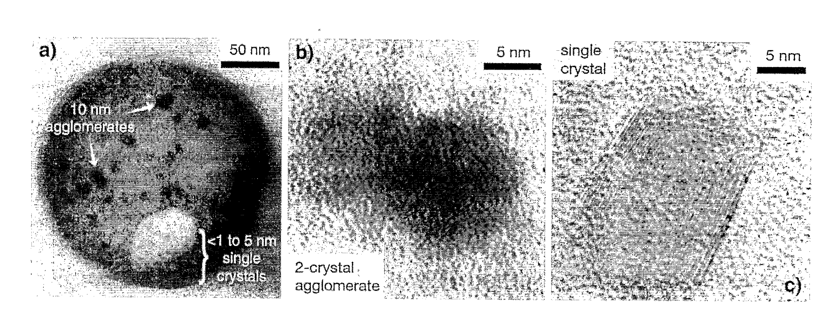
[0064]Based on analogy to polymer step-growth mechanisms, stoichiometric parity between reactants is a condition for large, uniform crystal growth (though the analogy is not exact because PB synthesis is a heterogeneous phase polymerization). If the reactant ratio is adjusted to include a large excess of a single reactant, it is possible to reduce crystal size. Our recipe employed a 5:1 molar ratio of potassium ferricyanide to iron(II) chloride. The simple reaction is shown in FIG. 4, with intercalated potassium ions within the crystal omitted for clarity. PB was synthesized by the addition of 35 mL of a 0.01 M aqueous solution of FeCl2 (Aldrich) dropwise to a 35 mL solution containing 0.05 M potassium ferricyanide (Aldrich) and 0.05 M KCl. After complete addition, the liquid was vigorously agitated for 1 min and then immediately subjected to ultrafiltration against a 3000 Da regenerated cellulose membrane to remove the large excess of potassium ferricyani...

example 2

Production of PB / LPEI Multi Layers

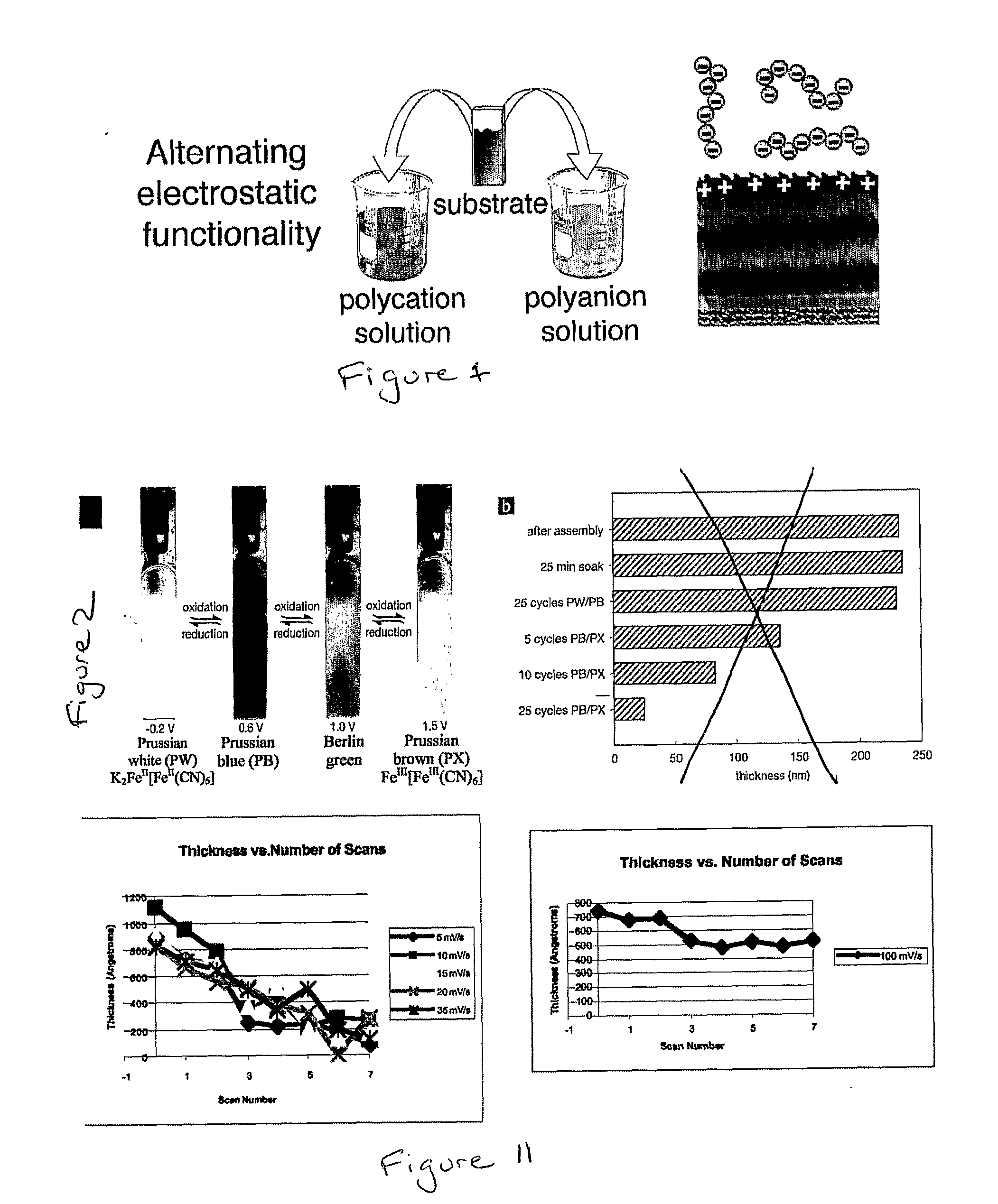
[0066]The anionically ionized PB suspension was LBL assembled with the weak (pH-sensitive) polycation linear poly(ethylene imine) (LPEI) at pH 4. We have previously shown that LPEI can increase ionic conductivity by two orders of magnitude over LBL films assembled using other weak polycations in films used as the solid or gel electrolyte layer in electrochemical power storage devices.[18] LPEI was therefore chosen for assembly with PB to capture this benefit for acceleration of electrochromic switching speed.

[0067]Aqueous solutions containing dissolved polycation LPEI (Poly-sciences MW 25 k) were formulated at 10 mM with respect to the poly-electrolyte equivalent weight (weight of ionized repeat unit). The pH was adjusted to pH4 using sodium hydroxide and hydrochloric acid solutions. ITO-glass substrates with dimensions 0.7 cm×5 cm (Delta Technologies, 6 Ω / square) were cleaned by ultrasonication in a series of solvents: dichloromethane, methanol, ac...

example 3

Electrochemical Analysis of PB / LPEI Multilayers

[0070]Once assembled, the LPEI / PB series was subjected to electrochemical analysis. Electrochemical analysis was performed using an EG&G 263 A potentiostat / galvanostat. These measurements were performed in a flat cell of 30 mL volume and approximately 0.3 cm2 working electrode area. The electrolyte used was aqueous 0.1 M potassium hydrogen phthalate with a pH of exactly 4. The counterelectrode was 4 cm2 platinum foil, and reference was a K-type saturated calomel electrode.

[0071]Cyclic voltammetry (CV) was performed around the potential range expected for the PW⇄PB transition: between −0.2 and 0.6 V at scan rates of 25, 50, 100, 200, and 400 mV s−1. Some representative CVs are shown in FIGS. 7A,B. They exhibit the reversible PW⇄PB transition at an E1 / 2 of approximately 0.15 V, a value consistent with PB electrochemistry described elsewhere, although slightly more cathodic than the 0.2 V that are typically reported.[19-21] The redox poten...


PUM


Abstract

A decomposable thin film comprising a plurality of alternating layers of net positive and negative charge. At least a portion of the positive layers, the negative layers, or both, comprise a polyelectrolyte.

Description

[0001]This application claims the priority of U.S. Provisional Application No. 60 / 650,613, filed Feb. 7, 2005, the contents of which are incorporated by reference herein.FIELD OF THE INVENTION[0002]This invention relates to layer-by-layer thin films that may be degraded by application of an electrical voltage.BACKGROUND OF THE INVENTION[0003]The ability to deliver multiple doses of drug in precise quantities to the body in a pre-programmed manner is highly desirable for a number of therapeutic applications. In particular, the regular delivery of toxic cancer drugs, potent therapeutics, anaesthetics or other agents to hard-to-reach regions of the body, such as the brain, is considered one of the most difficult challenges in the world of drug delivery. Many regimens require the repeated administration of the drug via oral intake or syringe injection at or near the desired site, thus requiring costly monitoring, the risk of missed dosages, and for delivery to difficult regions such as ...

Claims


Application Information

Patent Timeline
Patent Type & Authority Applications(United States)
IPC IPC(8): A61N1/30A61K9/70
CPCA61K9/0009
Inventor WOOD, KRISZACHARIA, NICOLEHAMMOND CUNNINGHAM, PAULADELONGCHAMP, DEAN
Owner MASSACHUSETTS INST OF TECH
Why Eureka
Try Eureka