Semiconductor substrate and semiconductor device and manufacturing method of the same
- Summary
- Abstract
- Description
- Claims
- Application Information
AI Technical Summary
Benefits of technology
Problems solved by technology
Method used
Image
Examples
embodiment mode 1
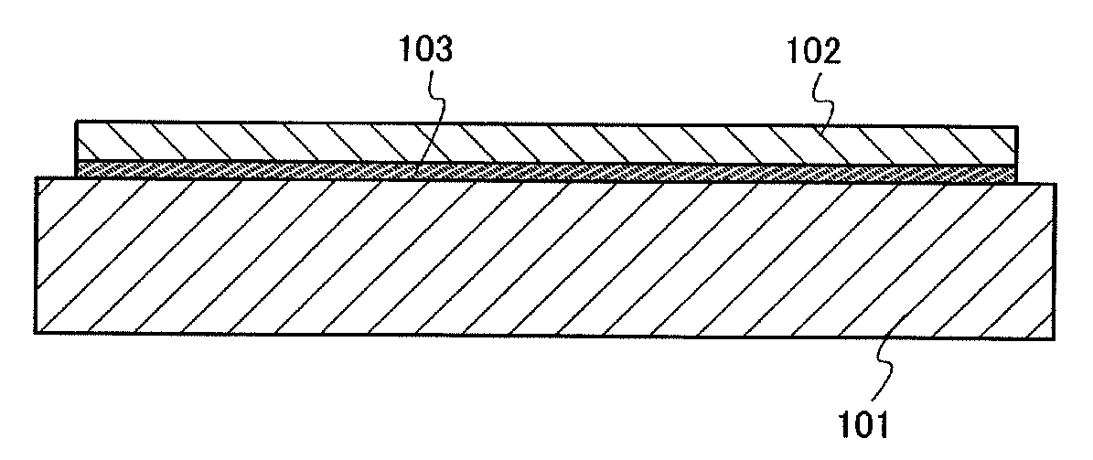
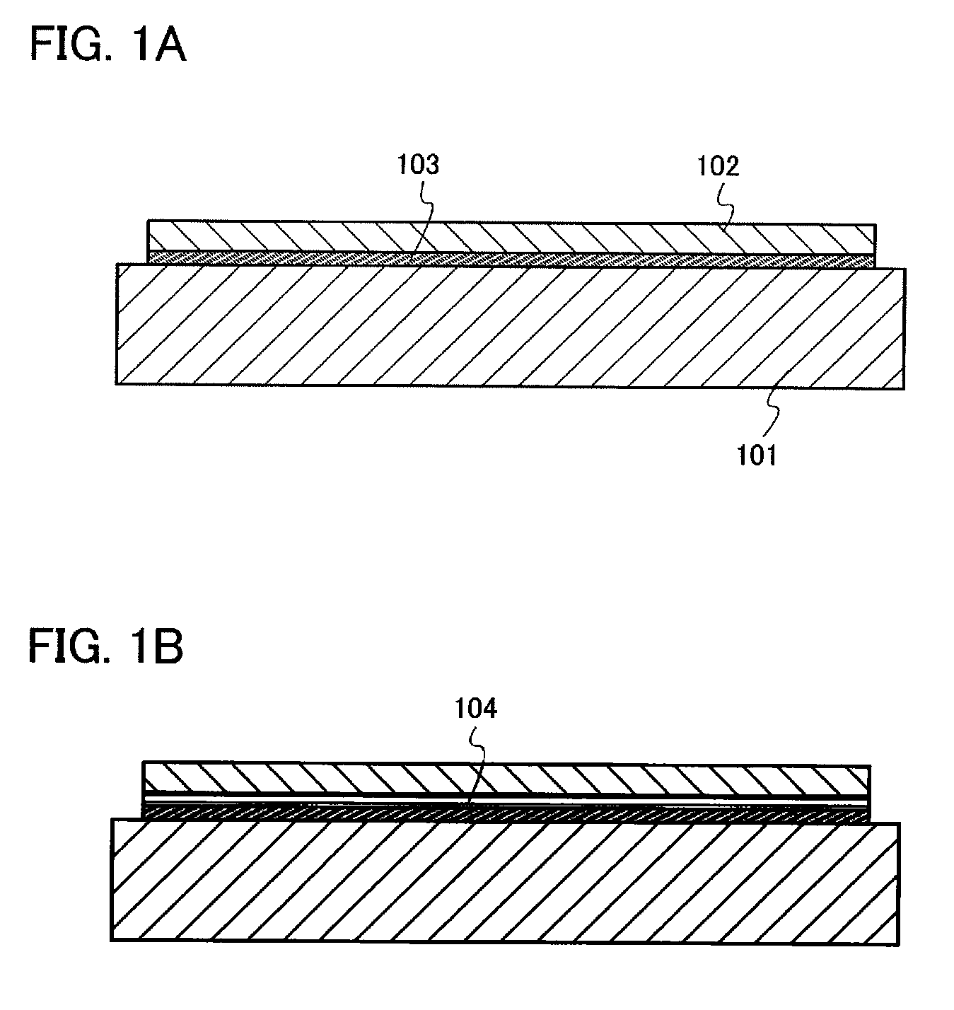
[0046]FIGS. 1A and 1B each show a semiconductor substrate according to the present invention. Note that, in this specification, a semiconductor substrate refers to a substrate in which a semiconductor layer is provided over a substrate having an insulating surface or an insulating substrate. Although the semiconductor layer is a single crystal semiconductor layer in many cases, a layer made of a polycrystal or a compound semiconductor may be used as well.
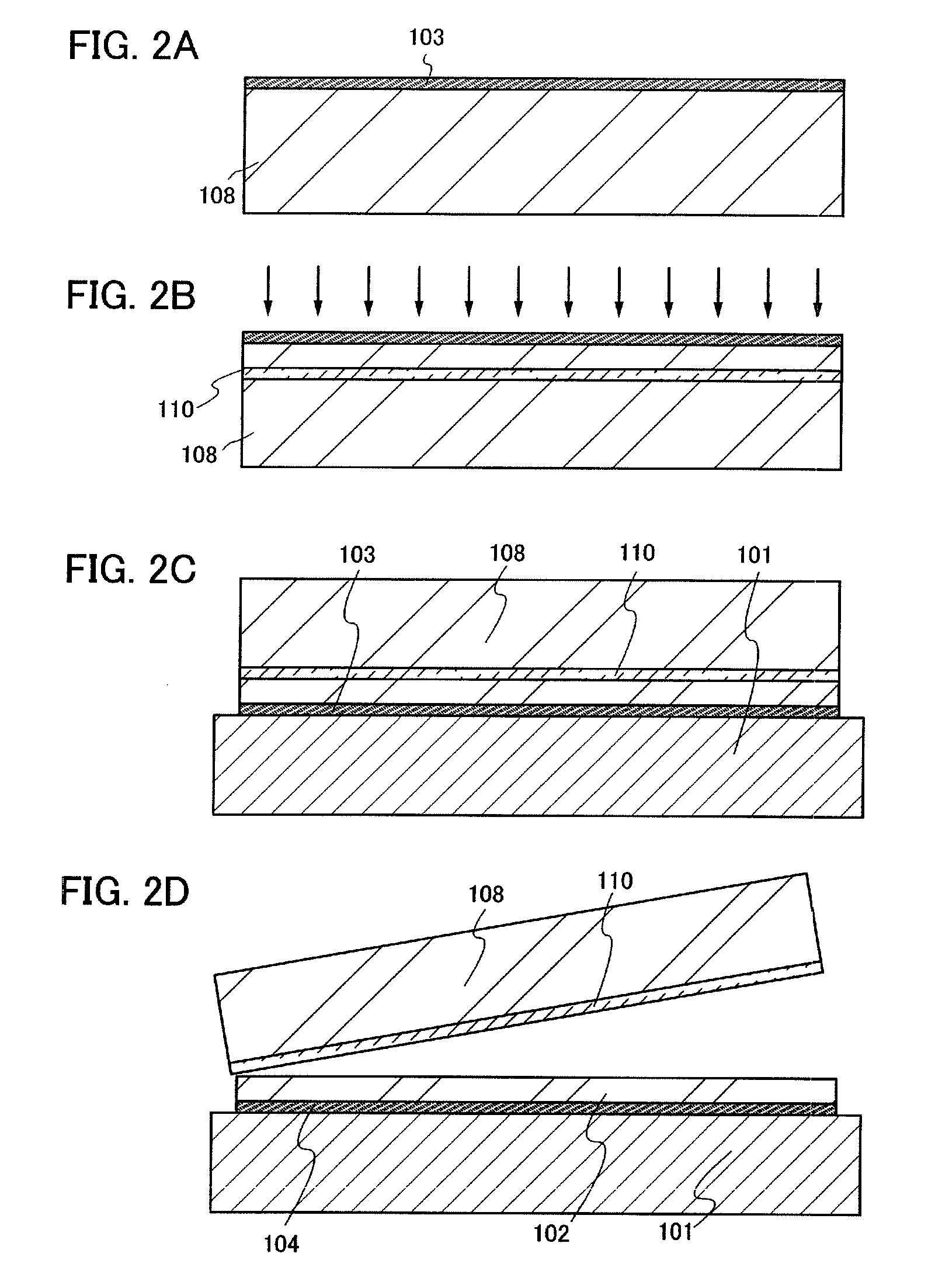
[0047]In FIG. 1A, a base substrate 101 is a substrate having an insulating surface or an insulating substrate, and any of a variety of glass substrates that are used in the electronics industry, such as an aluminosilicate glass substrate, an aluminoborosilicate glass substrate, and a barium borosilicate glass substrate, can be used. As the glass substrate, it is preferable to use a glass substrate having a coefficient of thermal expansion which is equal to or higher than 25×10−7 / ° C. and equal to or lower than 50×10−7 / ° C. (more pre...
embodiment mode 2
[0118]In this embodiment mode, a CMOS (complementary metal oxide semiconductor) will be described as an example of the semiconductor device of the present invention, using FIGS. 4A to 4E and FIGS. 5A to 5D. A method for manufacturing the semiconductor device will be described at the same time. According to this embodiment mode, a CMOS is manufactured using the semiconductor substrate described in Embodiment Mode 1 so that a CMOS with high performance and stable operation can be provided. Note that repetitive description for the same components as or components having similar functions to the components in Embodiment Mode 1 is omitted.
[0119]In FIG. 4A, the bonding layer 103, the barrier layer 104, and the semiconductor layer 130 are formed over the base substrate 101. Although the semiconductor substrate in which the barrier layer 104 for preventing one or both of phosphorus and boron contained in the bonding layer 103 from diffusing into the semiconductor layer is provided in this e...
embodiment mode 3
[0146]In this embodiment mode, a liquid crystal display device will be described as an example of the semiconductor device of the present invention, using FIGS. 6A and 6B. According to this embodiment mode, a liquid crystal display device is manufactured using the semiconductor substrate described in Embodiment Mode 1 so that a liquid crystal display device with high performance and stable operation can be provided.
[0147]FIG. 6A is a top view of the liquid crystal display device, and FIG. 6B is a cross-sectional view of FIG. 6A taken along line C-D.
[0148]As shown in FIG. 6A, a pixel region 306 and driver circuit regions 304a and 304b which are scanning line driver circuits are sealed between a base substrate 310 and a counter substrate 395 with a sealant 392. A driver circuit region 307 which is a signal line driver circuit including a driver IC is provided over the base substrate 310. A transistor 375 and a capacitor 376 are provided in the pixel region 306. A driver circuit includ...
PUM
 Abstract
Description
Claims
Application Information
 - R&D
- Intellectual Property
- Life Sciences
- Materials
- Tech Scout
- Unparalleled Data Quality
- Higher Quality Content
- 60% Fewer Hallucinations
Browse by: Latest US Patents, China's latest patents, Technical Efficacy Thesaurus, Application Domain, Technology Topic, Popular Technical Reports.
© 2025 PatSnap. All rights reserved.Legal|Privacy policy|Modern Slavery Act Transparency Statement|Sitemap|About US| Contact US: help@patsnap.com


