

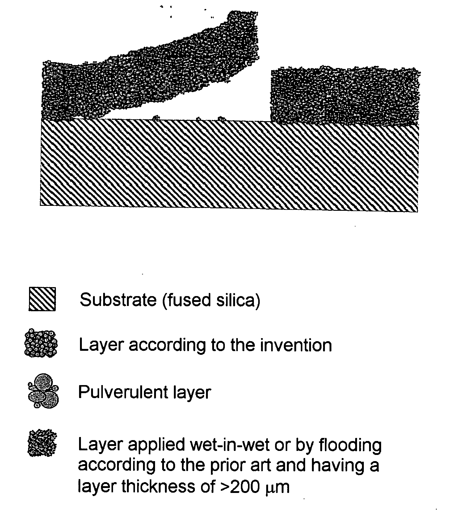
Firmly adhering silicon nitride-containing release layer
a silicon nitride and release layer technology, applied in the field of si3n4containing slip, can solve the problems of force wetting or infiltration low mechanical stability of the coating, and inability to adhere to the surface of the porous silicon nitride powder layer, so as to reduce the sinter activity of the binder, reduce the stress of the coating, and reduce the sinter activity
- Summary
- Abstract
- Description
- Claims
- Application Information
AI Technical Summary
Benefits of technology
Problems solved by technology
Method used
Image

Examples
example 1
[0118]The intermediate 1 is produced by homogenization of 3000 g of Inosil S-B (Inosil grade S-B 38 from Inomat GmbH: this commercially available binder is a mixture of organosilicon compounds, i.e. SiO2 precursors, and SiO2 nanoparticles), 1000 g of ethanol, 4000 g of silicon nitride powder (UBE E10) and 400 g of PVB (polyvinyl butyral BM 18, Wacker) by means of silicon nitride milling media in a PE container on a set of rollers.
[0119]The intermediate 2 is produced by pouring intermediate 1 into a flat PE container and drying in an explosion-protected drying oven. The binder is removed from the lumpy granular material at 450° C. in air in a fused silica crucible. To produce intermediate 3, the granules are ignited in a heat treatment at 900° C. in a covered crucible for one hour. 500 g of ethanol and 750 g of intermediate 3 are milled and homogenized in a PE container by means of SN milling media to produce intermediate 4. The average particle size of intermediate 4 is 4 μm. The in...
example 2
[0121]The intermediate 1 is produced by homogenization of 3000 g of Inosil S-B, 1000 g of ethanol, 4000 g of UBE E10 and 100 g of PVB by means of silicon nitride milling media in a PE container on a set of rollers.
[0122]The intermediate 2 is produced by spray granulation of intermediate 1. The binder is removed from the granular material at 450° C. in air in a fused silica crucible. To produce intermediate 3, the granules are ignited in a heat treatment at 900° C. in a covered crucible for one hour. 500 g of ethanol and 750 g of intermediate 3 are milled and homogenized in a PE container by means of milling media to produce intermediate 4. The average particle size of intermediate 4 is 5-6 μm. The intermediate 4 is applied in a layer thickness of about 300 μm to a fused silica crucible by flooding once. The layer is dried in air for 24 hours and subsequently fired at 1125° C. with a heating and cooling time of 8 hours.
[0123]The coating is defect-free and not powdery. The binder cont...
example 3
[0124]The intermediate 1 is produced by homogenization of 3000 g of Inosil S-B, 1000 g of ethanol, 4000 g of UBE E10 and 100 g of PVB by means of silicon nitride milling media in a PE container on a set of rollers. The intermediate 2 is produced by spray granulation of intermediate 1. The binder is removed from the granular material at 450° C. in air in a fused silica crucible. To produce intermediate 3, the granules are ignited in a heat treatment at 900° C. in a covered crucible for one hour. 600 g of ethanol and 750 g of intermediate 3 are milled and homogenized in a PE container with addition of 75 g of PEG 400 and 75 g of PVB by means of milling media to produce intermediate 4. The average particle size of intermediate 4 is 5 μm. The intermediate 4 is applied in a layer thickness of about 350 μm to a fused silica crucible by means of wet-in-wet spraying. The layer is dried in air for 24 hours and subsequently fired at 1125° C. with a heating and cooling time of 8 hours.
[0125]Th...
PUM
| Property | Measurement | Unit |
|---|---|---|
| temperature | aaaaa | aaaaa |
| temperature | aaaaa | aaaaa |
| temperature | aaaaa | aaaaa |
Abstract
Description
Claims
Application Information