Sheathed glow plug

a glow plug and shielding technology, applied in the field of shielding glow plugs, can solve the problems of unsuitable o-ring seals, potential oxidizing resistance elements, overheating of wires, etc., and achieve the effect of improving resistance to environmental degradation and hermeticity

a glow plug and shielding technology, applied in the field of shielding glow plugs, can solve the problems of unsuitable o-ring seals, potential oxidizing resistance elements, overheating of wires, etc., and achieve the effect of improving resistance to environmental degradation and hermeticity

US20090184101A1Inactive Publication Date: 2009-07-23FEDERAL MOGUL IGNITION

Image

  • Sheathed glow plug
  • Sheathed glow plug
  • Sheathed glow plug

Examples


Embodiment Construction

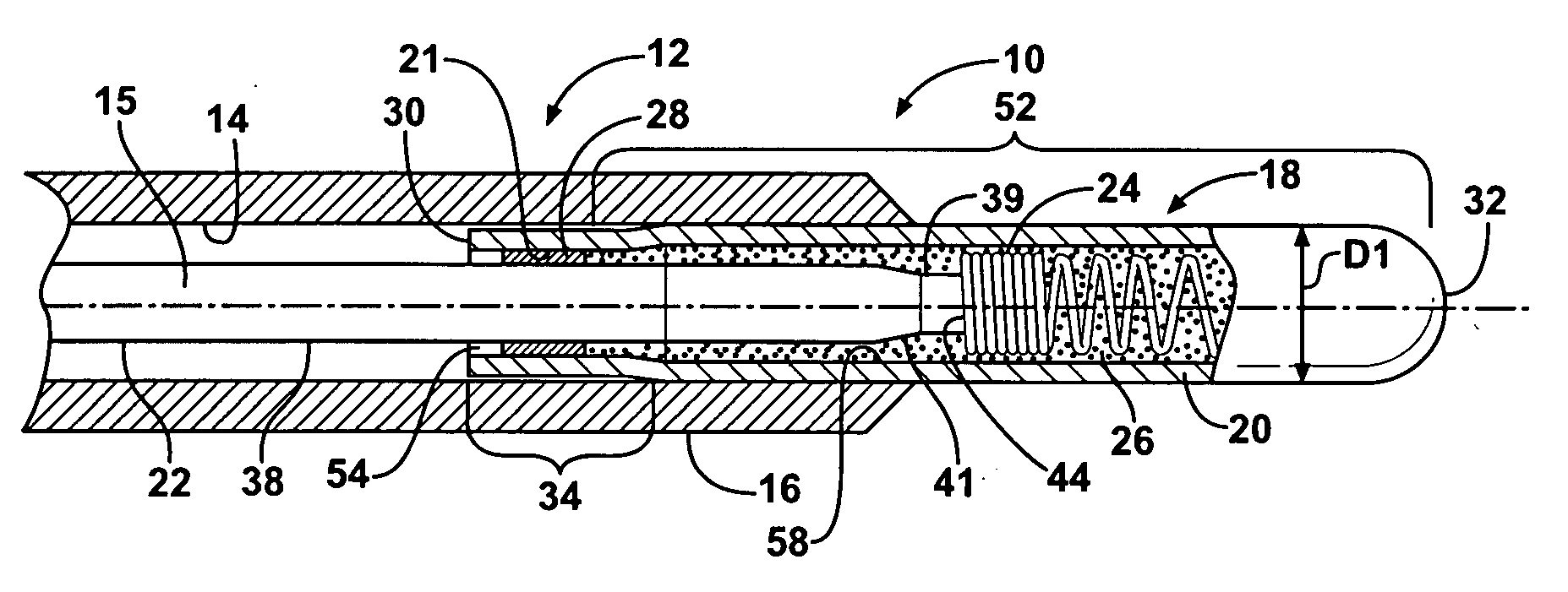
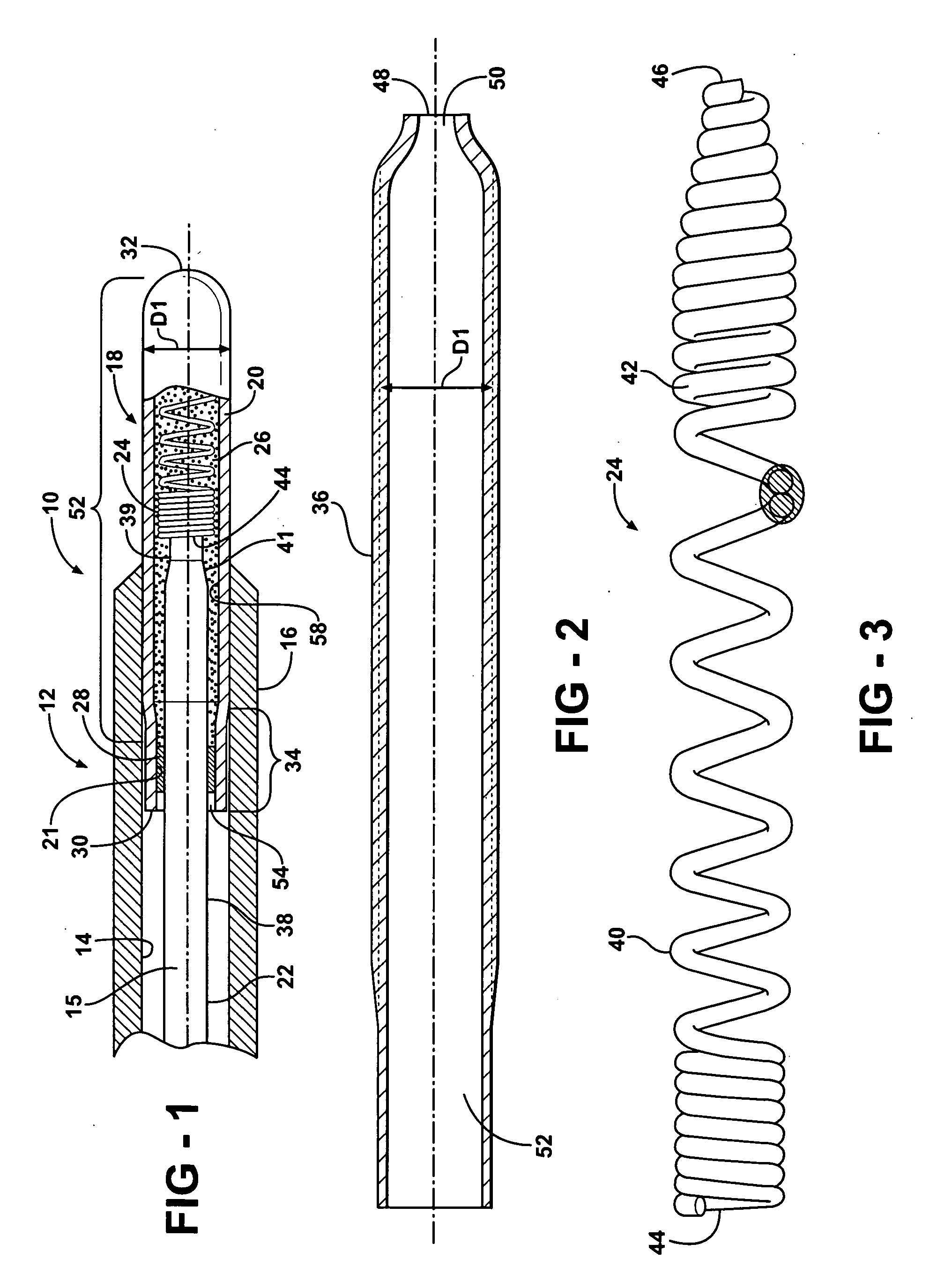
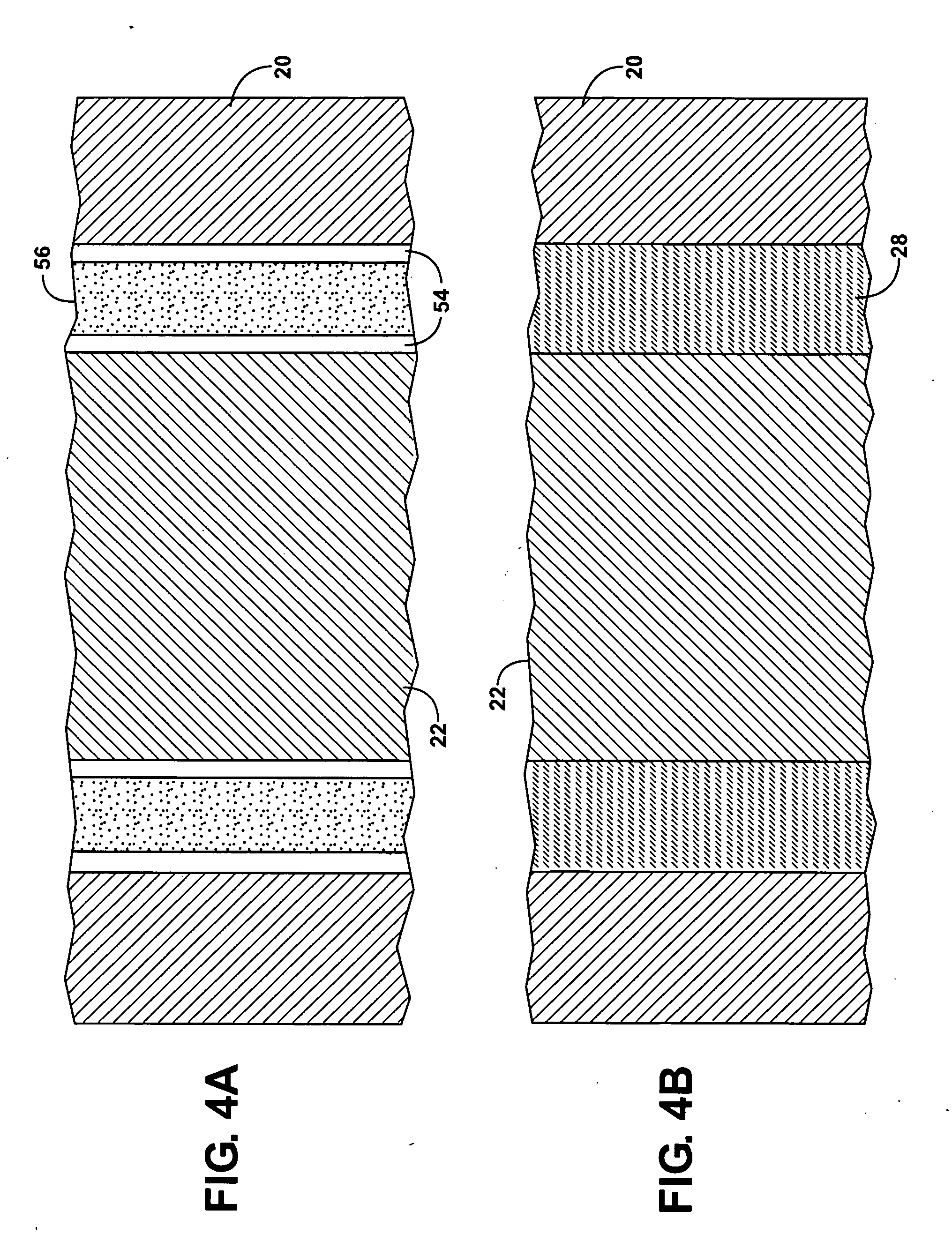
[0034]This invention provides a glow plug with an improved seal and heating element assembly which reduces the exposure of the thermally conductive and electrically insulating powder and spiral wire heating element that is embedded in the powder to oxygen and water vapor, thereby eliminating or substantially reducing the degradation processes described above. In glow plugs of the invention the components are processed in such a way that oxygen and water vapor are removed or substantially reduced within the powder bed during the installation of the seal. Once installed, the seal eliminates or greatly reduces the ability of the ambient atmosphere, which includes oxygen and water vapor, to permeate the insulating powder and reach the wire heating element, thereby inhibiting the potential for degradation of the wire heating element as described above.

[0035]Glow plugs and glow plug heater assemblies of the invention utilize a glass or glass-ceramic seal in lieu of an elastomeric or plast...


PUM

PropertyMeasurementUnit
operating temperatureaaaaaaaaaa
operating temperaturesaaaaaaaaaa
diameteraaaaaaaaaa

Abstract

A glow plug which includes an annular metal shell, thermally conductive tubular sheath, central electrode; resistance heating element, and electrically insulating, thermally conductive powder includes a glass seal in sealing engagement with the sheath and the electrode to form a sealed cavity within the sheath. The glass seal may include silicate, borate and borosilicate glasses, and may include one or more transition metal oxides, such as oxides of chromium, cobalt, nickel, iron and copper. The glass may also include a filler, including a ceramic oxide, such as one selected from a group consisting of quartz, eucryptites, leucites, cordierites, beta-spodumene, glass-ceramics, low-expansion glass(CTE<5 ppm / ° C.), mullite, zircon, zirconia and alumina. The sealed cavity may house a protective inert gas. The resistance heating element may be formed from a metal selected from a group consisting of tungsten, molybdenum, or alloys containing tungsten, molybdenum, nickel, iron, tantalum, niobium, titanium, vanadium, osmium and chromium.

Description

CROSS-REFERENCE TO RELATED APPLICATION[0001]This application claims the benefit of U.S. Provisional Application Ser. No. 61 / 014,122, filed Dec. 17, 2007, and U.S. Provisional Application Ser. No. 61 / 061,387, filed Jun. 13, 2008, both of which are incorporated herein by reference in their entirety.BACKGROUND OF THE INVENTION[0002]1. Technical Field[0003]This invention relates generally to glow plugs and, more particularly, to sheathed glow plugs.[0004]2. Related Art[0005]Sheathed glow plugs, such as those used in diesel engine applications, generally have an electrical resistance heater which includes one or more resistance elements, such as a spiral wound resistive wire, which is embedded in an electrically insulating, thermally conductive powder, e.g., magnesium oxide, so as to be electrically insulated from the tubular sheath they are located in, except for electrical connection with a free closed end of the tubular sheath. Glow plugs using a single electrical resistance element m...

Claims


Application Information

Patent Timeline
23 Jul 2009
Publication
US20090184101A1
IPC
F23Q7/22
CPC
F23Q7/001
Inventors
HOFFMAN, JOHN; GORETTI, SANDRO