
Non-aqueous electrolyte secondary battery, negative electrode material, and making method

a secondary battery and negative electrode technology, applied in the field of non-aqueous electrolyte secondary batteries, can solve the problems of difficult control of cooling rate, failure to take full advantage of the potential battery capacity of silicon, and failure to overcome the outstanding problems of silicon negative electrodes, etc., to achieve low 1st cycle charge/discharge efficiency of silicon oxide, improve cycle performance, and high battery capacity

Active Publication Date: 2009-09-24
SHIN ETSU CHEM IND CO LTD
View PDF19 Cites 167 Cited by
  • Summary
  • Abstract
  • Description
  • Claims
  • Application Information

AI Technical Summary

Benefits of technology

The invention provides a negative electrode material for non-aqueous electrolyte secondary batteries that has a high battery capacity per volume and improved cycle performance. The material comprises silicon oxide particles and polycrystalline silicon particles, which work together to increase the battery capacity without adding excessive volume expansion. The material also has improved conductivity and does not lose conductivity on charge / discharge cycles. The negative electrode material can be used in non-aqueous electrolyte secondary batteries to improve their performance.

Problems solved by technology

However, the negative electrode material therein uses 30 parts of a silicon component and 55 parts of graphite as the conductive agent as described in Example, failing to take full advantage of the potential battery capacity of silicon.
The provision of particle surfaces with a carbon layer improves conductivity, but is not successful in overcoming the outstanding problems of silicon negative electrodes, i.e., in mitigating substantial volumetric changes associated with charge / discharge cycles or in preventing electricity collection and cycle performance from degrading.
As for the polycrystalline silicon having grain boundaries, the disclosed method is difficult to control the cooling rate and hence, to reproduce consistent physical properties.
Nevertheless, silicon oxide has a substantial irreversible capacity and a very low initial efficiency of about 70%, which requires an extra battery capacity of the positive electrode when a battery is actually fabricated.
The problem of silicon oxide to be overcome prior to practical use is a substantially low initial efficiency.
As for the attachment of a lithium foil, a thin lithium foil that matches with the initial efficiency of silicon oxide negative electrode is hardly available or prohibitively expensive if available.
The deposition of lithium vapor makes the fabrication process complex and is impractical.
The method of obtaining the mixed solids by simultaneously generating silicon and silicon oxide vapors suffers from the working problem that the low vapor pressure of silicon necessitates the process at a high temperature in excess of 2,000° C.
As discussed above, the silicon-based active material still has a problem to be solved prior to practical use, independent of whether it is based on a metal element or an oxide thereof.

Method used


Image

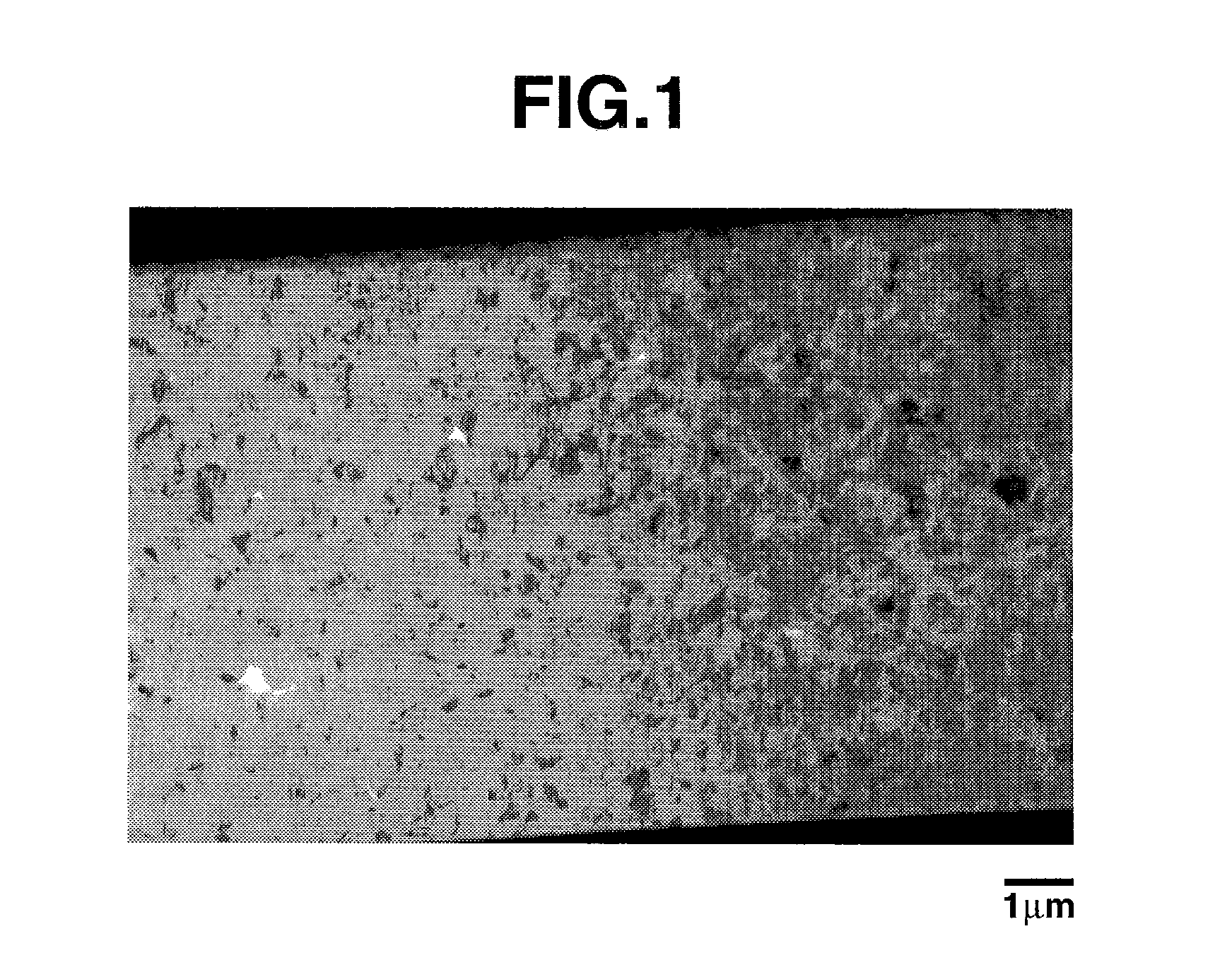
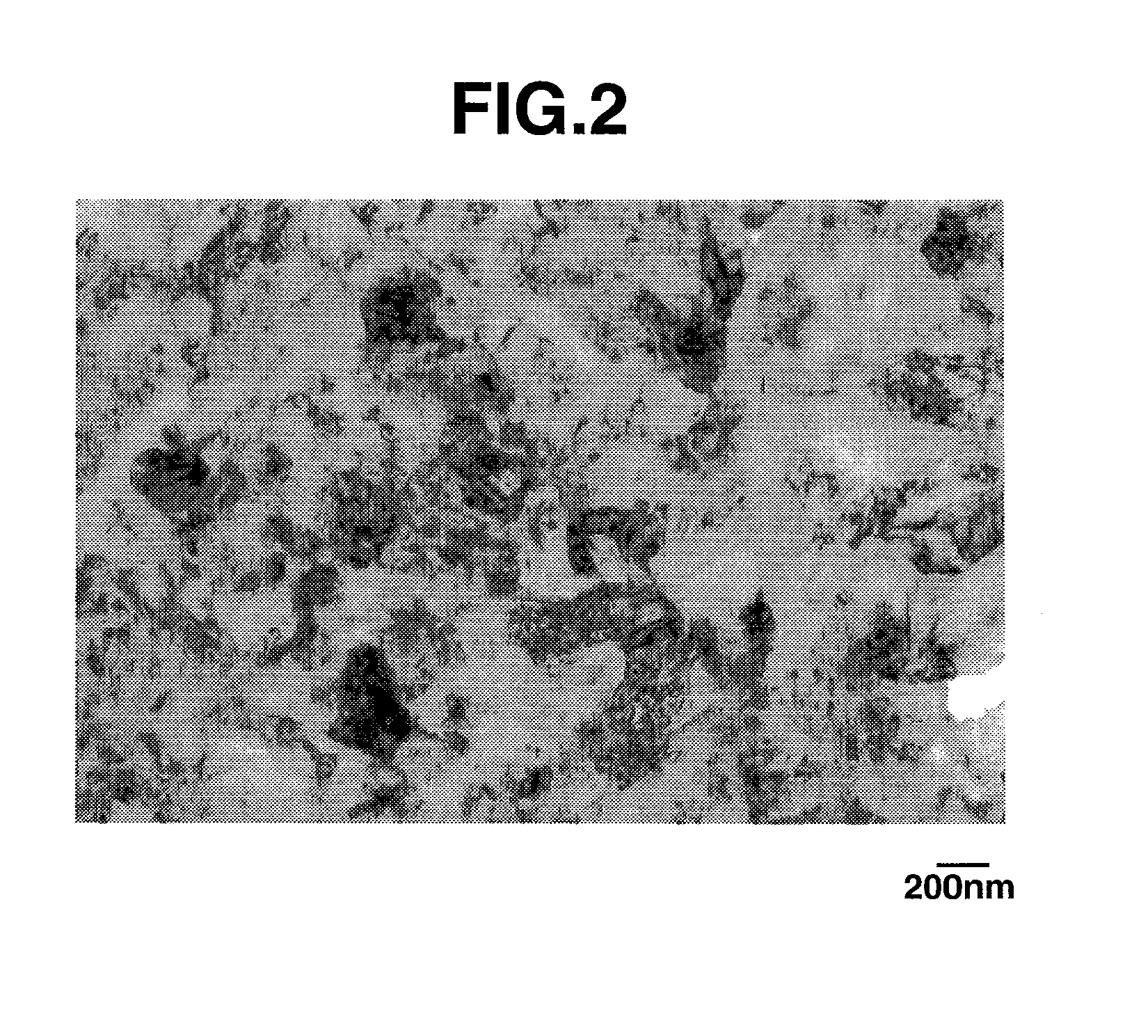
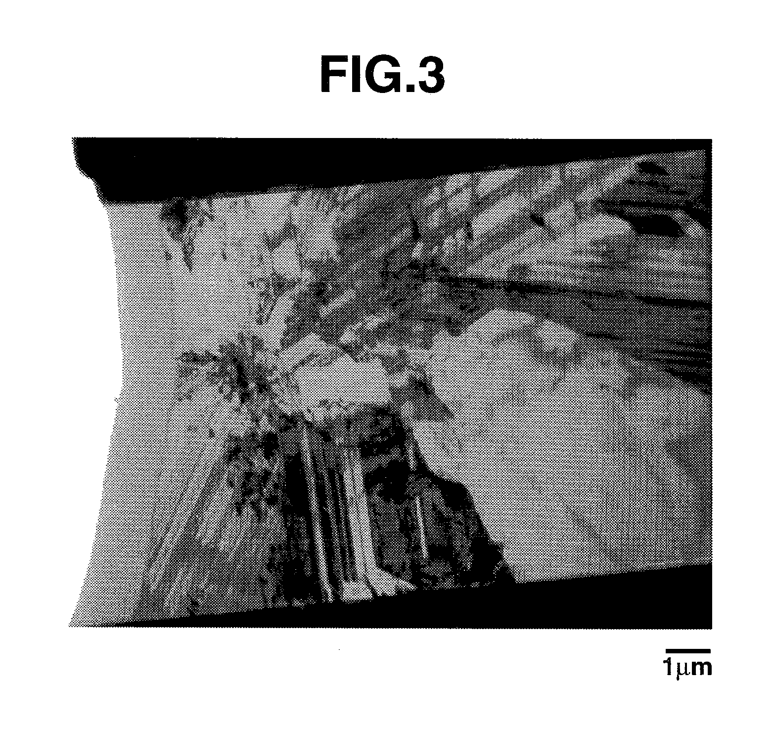
  • Non-aqueous electrolyte secondary battery, negative electrode material, and making method
  • Non-aqueous electrolyte secondary battery, negative electrode material, and making method
  • Non-aqueous electrolyte secondary battery, negative electrode material, and making method

Examples


example

[0117]Examples are given below for further illustrating the invention, but they are not to be construed as limiting the invention thereto. In Examples, all percents (%) are by weight, and the particle size is a median diameter D50 as determined by a particle size distribution instrument utilizing laser light diffractometry. In Tables, silicon oxide, polycrystalline silicon, and silicon particles are abbreviated as SiO, p-Si, and Si particles, respectively. A jet mill AFG-100 is available from Hosokawa Micron Group, and a classifier TC-15 is available from Nisshin Engineering Co., Ltd.

Preparation of Silicon Oxide Particles I-1

[0118]A mixture of equimolar amounts of silicon dioxide particles (BET specific surface area=200 m2 / g) and chemical grade metallic silicon particles (BET specific surface area=4 m2 / g) was heat treated in a hot vacuum atmosphere at 1,350° C. and 0.1 Torr to produce silicon oxide gas, which precipitated on a stainless steel substrate held at 1,000° C. The precipit...

examples 10 to 14

, Reference Example 1 & Comparative Example 2

[0143]A mixture of coated silicon oxide particles and silicon particles, prepared above, was diluted with N-methylpyrrolidone. A polyimide resin (solids 18.1%) as a binder was added thereto to form a slurry. The slurry was coated onto a copper foil of 12 μm thick by means of a doctor blade having a gap of 50 μm, vacuum dried at 200° C. for 2 hours, and pressed by a roller press at 60° C. into a negative electrode shaped form. Finally, pieces of 2 cm2 were punched out of the shaped form and used as a negative electrode. The composition of solid components is shown in Table 4.

Determination of Battery Properties

[0144]To confirm the effectiveness of the negative electrode material, the charge / discharge capacity and volume expansion of the material were measured as follows. Six lithium ion secondary cells were fabricated using the shaped form as the negative electrode and a lithium foil as the counter electrode. The electrolytic solution was a...


PUM

PropertyMeasurementUnit
crystallite sizeaaaaaaaaaa
specific gravityaaaaaaaaaa
temperatureaaaaaaaaaa

Abstract

A negative electrode material comprising an active material and 1-20 wt % of a polyimide resin binder is suitable for use in non-aqueous electrolyte secondary batteries. The active material comprises silicon oxide particles and 1-50 wt % of silicon particles. The negative electrode exhibits improved cycle performance while maintaining the high battery capacity and low volume expansion of silicon oxide. The non-aqueous electrolyte secondary battery has a high initial efficiency and maintains improved performance and efficiency over repeated charge / discharge cycles by virtue of mitigated volumetric changes during charge / discharge cycles.

Description

CROSS-REFERENCE TO RELATED APPLICATION[0001]This non-provisional application claims priority under 35 U.S.C. §119(a) on Patent Application Nos. 2008-067073 and 2008-109769 filed in Japan on Mar. 17, 2008 and Apr. 21, 2008, respectively, the entire contents of which are hereby incorporated by reference.TECHNICAL FIELD[0002]This invention generally relates to non-aqueous electrolyte secondary batteries, typically lithium ion secondary batteries. Specifically, it relates to negative electrode materials for use in such batteries and more particularly, to negative electrode materials comprising silicon oxide and silicon as an active material, and negative electrodes made thereof.BACKGROUND ART[0003]In conjunction with the recent rapid advances of portable electronic equipment and communications instruments, non-aqueous electrolyte secondary batteries having a high energy density are strongly demanded from the aspects of cost, size and weight reductions. A number of measures are known in ...

Claims


Application Information

Patent Timeline
Patent Type & Authority Applications(United States)
IPC IPC(8): H01M4/58B05D5/12H01M10/36
CPCH01M4/0428H01M4/134H01M4/1395H01M4/364H01M4/366Y02E60/122H01M4/483H01M4/622H01M4/625H01M10/0525H01M4/38H01M4/386Y02E60/10H01M4/02H01M4/04H01M4/58H01M10/05
Inventor NAKANISHI, TETSUOWATANABE, KOICHIROFUKUOKA, HIROFUMI
Owner SHIN ETSU CHEM IND CO LTD
Learn More