Laser scanning digital camera with simplified optics and potential for multiply scattered light imaging

a technology of scattered light and scanning digital camera, which is applied in the field of simplified optics of laser scanning digital camera with potential for multiply scattered light imaging, can solve the problems of permanent vision loss in an area, none of the neural cells of the retina can be readily made to readily regenerate in the adult human, and human retina is susceptible to damage from a variety of causes, etc., to achieve easy storage, transmission or printing, and low cost.

Active Publication Date: 2009-10-01
INDIANA UNIV RES & TECH CORP
View PDF9 Cites 65 Cited by
  • Summary
  • Abstract
  • Description
  • Claims
  • Application Information

AI Technical Summary

Benefits of technology

[0014]The present application relates to a device designed as an improved digital retinal imaging device. In particular, the present application relates to a laser scanning digital camera (“LSDC”) intended to be smaller and / or lower in cost than previous devices, while retaining a user-friendly format that allows a non-professional to obtain a high quality digital retinal image that can be easily stored, transmitted, or printed. In addition, according to another embodiment of the present application, the improved digital retinal imaging device may be used as a general imaging device or to improve image contrast in microscopy. Further, according to another embodiment of the present application, the additional aperture configurations and image processing capabilities provide a means for providing multiply scattered light images, which are useful for detecting structures that hidden under highly reflective tissue (e.g., deep retinal or choroidal disease underlying the vitreo-retinal interface and nerve fiber layer). In addition, according to certain embodiments of the present application, the device allows for increased illumination and / or light return at the edges of the field of view, thereby allowing for a more consistent, high contrast image to be produced. Finally, according to certain embodiments of the present application, a system and device allow for an increase in field size over previous embodiments, thereby allowing quality images to be taken even if the user is not adept at accurately aligning the imaging device with the eye.

Problems solved by technology

The human retina is susceptible to damage from a variety of environmental factors, including laser light impact and other trauma, as well as disease.
In fact, none of the neural cells of the retina can yet be made to readily regenerate in the adult human.
When damage is severe enough, there is permanent vision loss in an area.
If the affected region is in the central macula, known as the fovea, then the ability to see fine detail, read at rapid rates, or recognize objects at great distances may be lost.
The peripheral areas of vision do not have sufficient sampling density to perform these tasks to the same degree.
One of the chief problems in early detection of damage has been the difficulty of imaging a small area of retina.
Regardless of the wavelength of light used, many of the past devices used flood illumination, producing images of the retina that often are subject to poor contrast due to long range scatter.
The long range scatter problem was identified to occur, not only from out of plane tissues, but also from the biological tissues that are inherently scattering, especially those within and near the retina.
Such improvements have greatly increased the contrast of the images produced, but typically require expensive, heavy equipment that must be operated by a specialist.
However, the optics used in confocal apertures can increase the complexity of the system, and high quality optics are an added expense.
Further, when implemented with scanning laser devices, infrared and near infrared imaging of sub-retinal structure in the ocular fundus has been able to reveal sub-retinal deposits, the optic nerve head, retinal vessels, choroidal vessels, fluid accumulation, hyperpigmentation, atrophy, and breaks in Bruch's membrane—features that have proven difficult or impossible to observe with flood illumination devices.
However, previous scanning devices, including those embodied in the patent applications submitted by the inventor and her colleagues, do not readily utilize this method for producing an image without scanning not only the light illuminating the target, but also scanning the light returning from the target to the detector, which requires considerable care.
Existing devices specifically designed for screening of retinal disease that use flood illumination with bright lights of shorter wavelengths, and typically acquire single images at slow rates, have been shown recently to provide an unacceptable percentage of gradable images in the hands of technicians (Zimmer-Galler I, Zeimer R. Results of implementation of the DigiScope for diabetic retinopathy assessment in the primary care environment.

Method used


Image

  • Laser scanning digital camera with simplified optics and potential for multiply scattered light imaging
  • Laser scanning digital camera with simplified optics and potential for multiply scattered light imaging
  • Laser scanning digital camera with simplified optics and potential for multiply scattered light imaging

Examples


Embodiment Construction

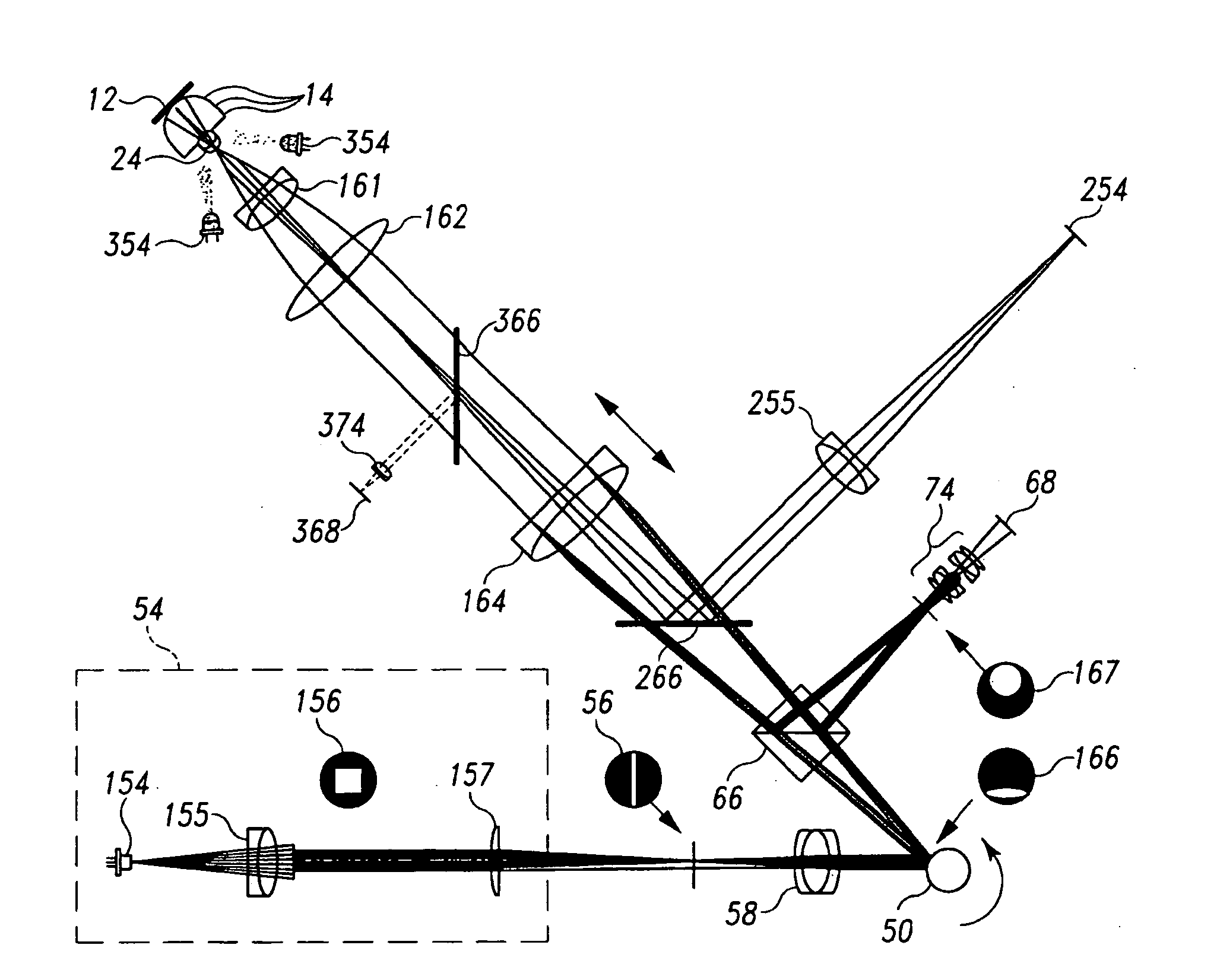
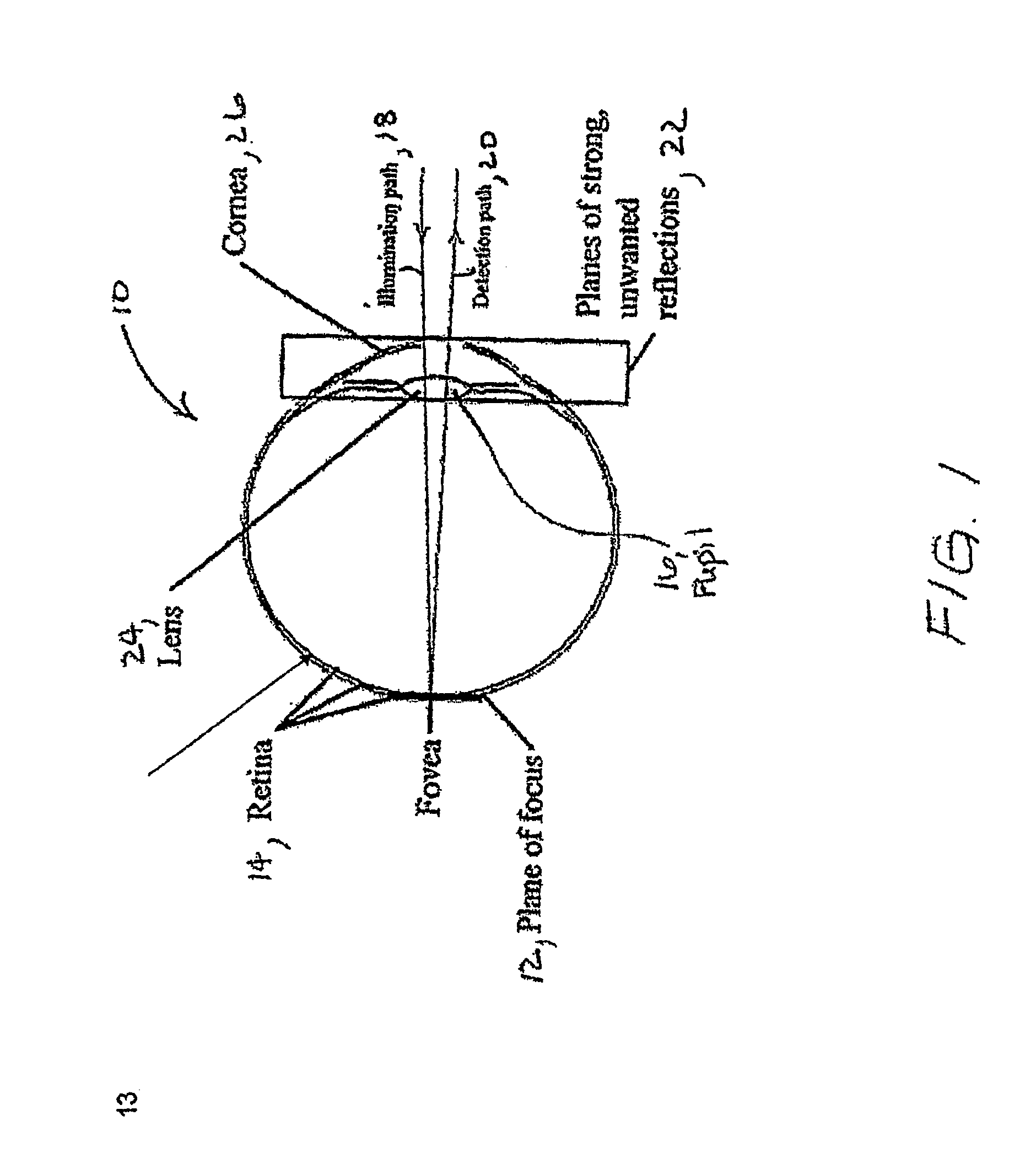
[0030]The present application relates to a small, portable lightweight instrument or device of low cost particularly suitable for examining the retinal and subretinal layers of the eye 10 (see FIG. 1) for abnormalities. The device is noncontact and does not require drops to dilate the pupil of the eye in order to obtain a retinal or sub-retinal image. Referring to FIG. 1, the plane of focus 12 of the device includes the vitreoretinal interface and the retinal nerve fiber layer, which have the greatest amount of light return of the several sublayers of the retina 14. This area of greatest light return is helpful in finding the plane of focus, but presents a problem when trying to image through that area of the retina 14. When a human retina 14 is imaged, light from an illumination source is passed through a slit aperture to produce a line source and scanned across a desired focal plane in the eye after passing through the entrance pupil 16 of the eye. Light enters through one or more...


PUM


Abstract

A portable, lightweight digital imaging device uses a slit scanning arrangement to obtain an image of the eye, in particular the retina. The scanning arrangement reduces the amount of target area illuminated at a time, thereby reducing the amount of unwanted light scatter and providing a higher contrast image. A detection arrangement receives the light remitted from the retinal plane and produces an image. The device is operable under battery power and ambient light conditions, such as outdoor or room lighting. The device is noncontact and does not require that the pupil of the eye be dilated with drops. The device can be used by personnel who do not have specialized training in the eye, such as emergency personnel, pediatricians, general practitioners, or volunteer or otherwise unskilled screening personnel. Images can be viewed in the device or transmitted to a remote location. The device can also be used to provide images of the anterior segment of the eye, or other small structures. Visible wavelength light is not required to produce images of most important structures in the retina, thereby increasing the comfort and safety of the device. Flexible and moderate cost confocal and fluorescent imaging, multiply scattered light images, and image sharpening are further functionalities possible with the device.

Description

CROSS REFERENCE TO RELATED APPLICATION[0001]The present application is a U.S. National Stage Application of International Patent Application Serial No. PCT / US07 / 12726, filed on May 30, 2007, the contents of which are herein incorporated by reference, which claims priority to U.S. Provisional Patent Application Ser. No. 60 / 809,551, filed on May 31, 2006, the contents of which are herein incorporated by reference.STATEMENT REGARDING FEDERALLY SPONSORED RESEARCH[0002]The work leading to the invention received support from the United States federal government under National Institutes of Health Grant No. EB002346. The federal government has certain rights in the invention.BACKGROUND OF THE INVENTION[0003]The human retina is susceptible to damage from a variety of environmental factors, including laser light impact and other trauma, as well as disease. Once damaged, the cells responsible for capturing light energy and transducing it into a neural signal, the photoreceptors, do not regene...

Claims


Application Information

Patent Timeline
Patent Type & Authority Applications(United States)
IPC IPC(8): A61B3/14
CPCA61B3/1025A61B3/156
Inventor ELSNER, ANN E.PETRIG, BENNO
Owner INDIANA UNIV RES & TECH CORP
Why Eureka
Try Eureka