
Composite porous membrane, method of producing composite porous membrane, and battery separator, battery and capacitor using the same

Inactive Publication Date: 2009-11-19
TOYO TOYOBO CO LTD
View PDF0 Cites 34 Cited by
  • Summary
  • Abstract
  • Description
  • Claims
  • Application Information

AI Technical Summary

Benefits of technology

[0012]The present invention has been devised to solve the above problems, and it is an object of the present invention to provide a composite porous membrane which is suited for a separator for a battery having excellent permeability, low pore blocking temperature and high membrane breakage temperature by combining resin porous membranes having different melting points (or softening points) without using a thermocompression bonding method or a method of directly applying a solution to a substrate.
[0016]According to the present invention, it is possible to provide a separator that is suited for a nonaqueous electrolyte secondary battery or a capacity, realizing high membrane breakage temperature and excellent safety without impairing ion permeability and a low-temperature pore blocking function that are inherently possessed by porous membrane A.

Problems solved by technology

However, when temperature continuously increases after blocking of pores for some reason, the membrane may break at a certain temperature due to a decrease in viscosity of melted polyethylene forming the membrane and contraction of the membrane.
Further, when the membrane is left still under a certain high temperature, it may break after a lapse of certain time due to a decrease in viscosity of melted polyethylene forming the membrane and contraction of the membrane.
However, in the method of bonding a heat resistant film having punched using laser beams, linear pores are inevitably formed from a front face to a back face, and these crater-like pores are distributed over a wide area, so that it is impossible to form a porous layer in the form of fine network similar to that of a current polyolefin porous membrane.
Further, when a composite membrane is produced by laminating a heat resistant porous membrane of polyimide, polyamideimide, polyamide and the like and a polyolefin porous membrane, it is difficult to form the porous membrane by the same drawing elongation method as in the case of polyolefin porous membrane because the glass transition temperature of a heat resistant resin is very high, and heat deterioration of a resin also occurs at a temperature around glass transition temperature, and hardening occurs by a self cross-linking reaction at a high temperature.
Further, it is very difficult to execute drawing elongation after bonding the heat resistant porous membrane and the polyolefin porous membrane to each other because there is a large difference in softening temperature.
Further, as to the method of thermocompression bonding heat a resistant film punched by laser beams or the like, significant deterioration in air permeability is inevitable because an opening area in the film itself is small, and most of the pores are blocked by blocking of a polyethylene surface at the time of thermocompression bonding.
In order to solve this problem, it is necessary to make porosity and surface porosity of the porous membrane to be combined higher, however, it accompanies the problem of embrittlement of mechanical property, decrease insulation and difficulty in fabrication of thin membrane.
Also known is a method of forming a heat resistant porous phase by a wet membrane forming method after applying a heat resistant resin solution to a polyolefin porous membrane, however, when this method is used, the coating solution internally permeates to a superficial layer part of the polyolefin porous membrane, inevitably leading deterioration in air permeability and reduction in a pore blocking function.
Further, since permeation of the coating solution is controlled by the weight and thixotropy of the coating solution, and capillary phenomenon caused by micropores of the polyolefin porous membrane, various physical properties of a producible composite porous membrane are largely restricted, and fundamental solution is difficult.

Method used


Image

  • Composite porous membrane, method of producing composite porous membrane, and battery separator, battery and capacitor using the same
  • Composite porous membrane, method of producing composite porous membrane, and battery separator, battery and capacitor using the same
  • Composite porous membrane, method of producing composite porous membrane, and battery separator, battery and capacitor using the same

Examples


example 1

[0116]To 100 parts by weight of a polyamideimide resin solution (HR11NN available from TOYOBO Co., Ltd., concentration of nonvolatile content: 15% NMP solution, glass transition temperature: 280° C.), 20 parts by weight of polyethylene glycol (PEG-400 available from Sanyo Chemical Industries Ltd.) was added and mixed to homogeneity at room temperature (Coating solution 1).

[0117]After applying the coating solution 1 on the surface having preliminarily subjected to a corona discharge treatment of a propylene film (pi-wren-OT available from TOYOBO Co., Ltd.) which is a substrate with a clearance of 30 μm and application speed of 1.0 m / min, the film was caused to pass through the atmosphere of 80% RH at 25° C. over 30 seconds, to obtain porous membrane B in semi-gel state.

[0118]On the semi-gel porous membrane B, a polyethylene porous film (thickness: 20 μm, porosity: 40%, air permeability: 300 sec / 100 cc Air) which is porous membrane A was laminated, and caused to enter in an aqueous so...

example 2

[0119]To 100 parts by weight of a polyamideimide resin solution (HR16NN available from TOYOBO Co., Ltd., concentration of nonvolatile content: 14% NMP solution, glass transition temperature: 320° C.), 15 parts by weight of polyethylene glycol (PEG-400 available from Sanyo Chemical Industries Ltd.) was added and mixed to homogeneity at room temperature (Coating solution 2).

[0120]After applying the coating solution 2 on the surface having preliminarily subjected to a corona discharge treatment of the propylene film (pi-wren-OT available from TOYOBO Co., Ltd.) which is a substrate with a clearance of 20 μm and application speed of 1.0 m / min, the film was caused to pass through the atmosphere of 80% RH at 25° C. over 30 seconds, to obtain porous membrane B in semi-gel state.

[0121]On the semi-gel porous membrane B, the polyethylene porous film (thickness: 10 μm, porosity: 47%, air permeability: 80 sec / 100 cc Air) which is porous membrane A was laminated. At this time, since tensile stren...

example 3

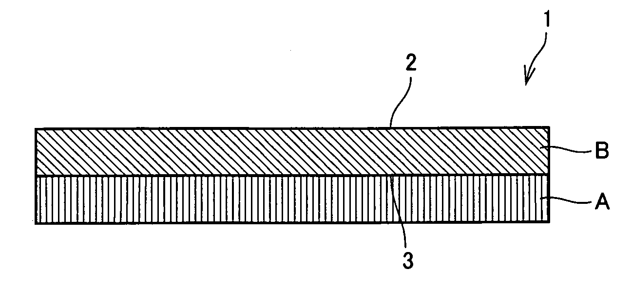
[0122]To a four-necked flask with a condenser and a nitrogen gas inlet, 0.5 mol of pyromellitic dianhydride, 0.5 mol of biphenyltetracarboxylic dianhydride, 0.5 mol of diphenylmethane-4,4′-diisocyanate and 0.5 mol of hexamethylene diisocianate were charged together with NMP so that solid concentration was 20%, and allowed to react at 150° C. for about one hour. The obtained solvent-soluble polyimide resin have a concentration of nonvolatile content of 20%, a logarithmic viscosity of 0.7 g / dl, and a glass transition temperature of 190° C. Composite porous membrane 1 as shown in FIG. 1 was obtained in the same manner as in Example 1 except that this polyimide resin solution was used.


PUM

PropertyMeasurementUnit
Temperatureaaaaaaaaaa

Abstract

The present invention provides a composite porous membrane suited for a separator for a battery having excellent ion permeability, low pore blocking temperature, and high membrane breakage temperature by compositing resin porous membranes having different melting points (or softening points) without using a termocompression bonding method or a method of directly applying a solution to the substrate by using a composite porous membrane containing a porous membrane A of a resin having a melting point of 150° C. or less and a porous membrane B of a resin having a glass transition temperature of more than 150° C. integrated with the porous membrane A, wherein both a superficial side of the porous membrane B and an interfacial side with the porous membrane A of the porous membrane B have a three-dimensional network structure.

Description

BACKGROUND OF THE INVENTION[0001]1. Field of the Invention[0002]The present invention relates to a composite porous membrane having both a pore blocking function and excellent resistance to membrane breakage at a high temperature. More specifically, the present invention relates to a composite porous membrane which is useful as a separator for a lithium ion battery with high safety and charging-discharging reaction stability, having excellent ion permeability, and realizing both pore blocking function at 150° C. or less and heat resistant membrane breakage temperature of 200° C. or more, and further to a battery or a capacitor using the same.[0003]2. Description of the Background Art[0004]A porous membrane (microporous membrane) made of a thermoplastic resin is widely used as materials intended for separation, selective permeation and isolation of substances, such as separators for a battery used, for example, in a lithium secondary battery, a nickel-hydrogen battery, a nickel-cadmi...

Claims


Application Information

Patent Timeline
IPC IPC(8): H01M2/16B32B27/08B32B5/32C08J7/02H01M50/406
CPCH01G9/02H01M10/0525H01M2/166H01M2/145Y10T428/24998Y10T428/249981Y02E60/10H01M50/446H01M50/406
Inventor NAKAJIMA, ATSUSHIINUKAI, CYUJIIRIE, MICHIHIKONAKAMURA, MASANORIYAMADA, JUN
Owner TOYO TOYOBO CO LTD
Learn More