Imaging Agents

Inactive Publication Date: 2009-12-03
AION DIAGNOSTICS
View PDF0 Cites 125 Cited by
  • Summary
  • Abstract
  • Description
  • Claims
  • Application Information

AI Technical Summary

Benefits of technology

[0030]According to a first aspect of the present invention, a method of imaging a human or animal subject is provided, where

Problems solved by technology

One difficulty in the use of imaging agents for procedures utilizing multiple imaging modalities is that an imaging agent, such as a tissue marker, that is detectable in and compatible with one imaging modality (e.g. x-ray) may not be detectable in or compatible with another imaging modality (e.g. MRI).
Alternatively, the marker may be detectable, but may cause substantial distortion or interference with images formed by certain imaging modalities.
Furthermore, certain markers may pose a safety risk to a patient exposed to certain imaging modalities such as MRI.
For example, conventional markers such as titanium markers or stainless steel, may be detectable in and compatible with x-ray and other non-magnetic field imaging modalities, but may not be compatible with images produced via magnetic field imaging modalities such as MRI.
More specifically, the interaction of the magnetic and/or conductive properties of the marker with the magnetic field applied during MRI may cause image distortion.
These materials may also pose a safety risk associated with the exposure of the marker to external or applied magnetic fields, such as movement of the marker within the body.
Another difficulty in the use of imaging agents for procedures utilizing multi

Method used


Image

  • Imaging Agents
  • Imaging Agents
  • Imaging Agents

Examples


example 1

[0234]An electronic grade single crystal silicon wafer of purity 99.99999%, 5-15 mΩ cm resistivity and 150 mm diameter is anodised at 30 mA / cm2 for 90 minutes. A much higher current density is then applied for a few seconds to create an underlying thin very high porosity layer that will facilitate removal of the thick porous silicon layer from the non-porous part of the wafer. Upon immersion of the anodised wafer in an alcohol rinse bath, the fully intact membrane is released. This generates a 67-75 vol % porosity, 145 μm thick mesoporous membrane. The membrane is then crushed into mm size granules, and jet milled and classified. This generates a porous silicon particulate product comprising electronic grade silicon of purity 99.999% having a broad distribution of particle size between 25 and 125 μm diameter. It is then treated in aqueous HF solution for ten minutes, washed in deionised water for ten minutes, before being air dried on filter paper for ten minutes, in order to remove...

example 2

[0235]A microparticle contrast agent suitable for use in the present invention is prepared as follows. Electronic grade polycrystalline silicon powder of purity 99.999% is jet milled and classified into a tight size distribution with a mean diameter of 1 μm, a d50 of 3 μm and a d90 of 5 μm. 50 g of the classified powder is subjected to a 36% HCl acid wash and water rinse. The dried batch is then stain etched to a porosity in the range 40-80 vol % using HF / Nitric acid solutions under temperature regulation. On completion, the reaction is quenched by addition of cold water, the slurry stirred for 2 minutes and the product isolated by filtration. Water rinsing is followed by acetone and ethanol rinsing. The porous particles are suspended in a suitable formulation that after sterilisation is ready for intravenous injection.

example 3

[0236]A range of samples were prepared for testing with ultrasound. These were as follows:

(a) Bulk silicon powder (Metallurgical Grade—MGSi);

(b) A powder comprising silicon and iron (FeSi);

(c) A multi-layer porous silicon powder (MpSi) produced from a membrane (200 repeats) with the powder being hand-milled from 5 to 10 minutes;

(d) High porosity porous silicon powder (HpSi). This sample was produced by anodising a p+ wafer in a standard electrolyte. The powder was produced when the porous silicon self-detached itself from the wafer during the drying process. It was milled by hand and the porosity was estimated to be greater than 85%.

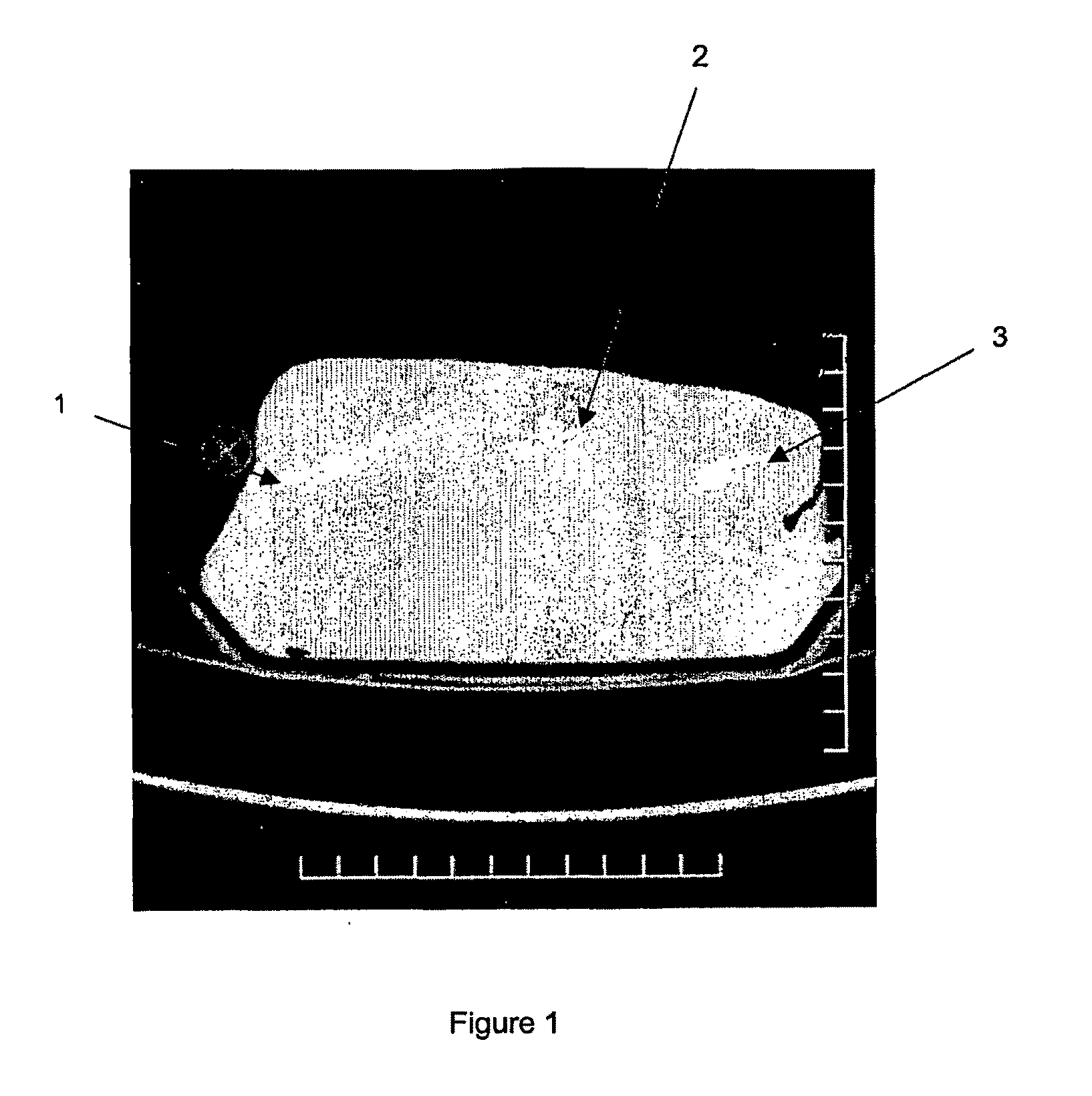
[0237]Ultrasound measurements were taken using an ESAOTE MEGAS ultrasound machine using a standard linear probe at a frequency of 7.5 MHz, and at a constant depth of 5 cm (2.5 cm focal point) and a power of 75%.

[0238]Each of the samples was injected in the form of a suspension into a poultry muscle. These were prepared by adding each of the silicon sampl...


PUM


Abstract

The use of silicon as an imaging agent is described.

Description

FIELD OF THE INVENTION[0001]The present invention relates to the use of silicon, in particular porous silicon (pSi), as an imaging agent for use in combination with one or more of a range of imaging techniques or modalities. In particular, the silicon imaging agent may be used as a contrast agent suitable for use in human or animal circulatory and other organ systems including the vasculature, respiratory, alimentary, lymphatic, musculoskeletal, reproductive, nervous and renal / urinary systems, and for marking skin and other tissues. The silicon imaging agent is also suitable for use in molecular imaging.BACKGROUND OF THE INVENTION[0002]Imaging agents are materials used to improve the visibility, in particular, the contrast, of internal bodily structures in an image generated using any one of a range of imaging techniques. These techniques or modalities include, but are not limited to, x-rays, computerised tomography (CT), magnetic resonance imaging (MRI), scintigraphy, fluorescence ...

Claims


Application Information

Patent Timeline
IPC IPC(8): A61K51/00A61K49/00A61K49/04
CPCA61K49/0043A61K49/0045A61K49/0047A61K49/0091A61K49/04A61K49/0419A61K51/1244A61K49/1818A61K49/1887A61K49/22A61K49/225A61B6/506A61K49/06A61K49/18
Inventor CANHAM, LEIGH TREVORKLUCZEWSKA, ANNA AGNIESZKABARLEY, JEROME PAULVARAJAO, RAPHAELA FORTES DRUMMOND CHICARINO
Owner AION DIAGNOSTICS
Why Eureka
Try Eureka