Electron source

Inactive Publication Date: 2010-02-04
DENKA CO LTD
View PDF3 Cites 29 Cited by
  • Summary
  • Abstract
  • Description
  • Claims
  • Application Information

AI Technical Summary

Benefits of technology

[0027]The electron source of the present invention has little surplus current, which does not sacrifice electrooptical characteristics for adjustme

Problems solved by technology

However, the above-mentioned known electron source suitable for high c

Method used


Image

  • Electron source
  • Electron source
  • Electron source

Examples


examples

[0079]Next, the present invention is more specifically described with an Example and a Comparative Example, but the present invention should not be construed as limited to the following Example.

example

[0080]A tungsten single crystal of orientation is cut into a rod of rectangular solid shape of 2 mm×0.4 mm×0.4 mm by electric discharge machining, and is fabricated into the shape of FIG. 3(c) by mechanical polishing. The apex is further polished with a diamond polishing agent to remove fabrication damage to provide an electron emitting portion 8 (FIG. 3(d)). The full apex angle 25 of a first truncated cone portion or cone portion 23 is 90°, and the full apex angle 24 of a second truncated cone portion 22 is 30°. Further, the shape of electron emitting portion 8 is circular and its diameter is 39 μm.

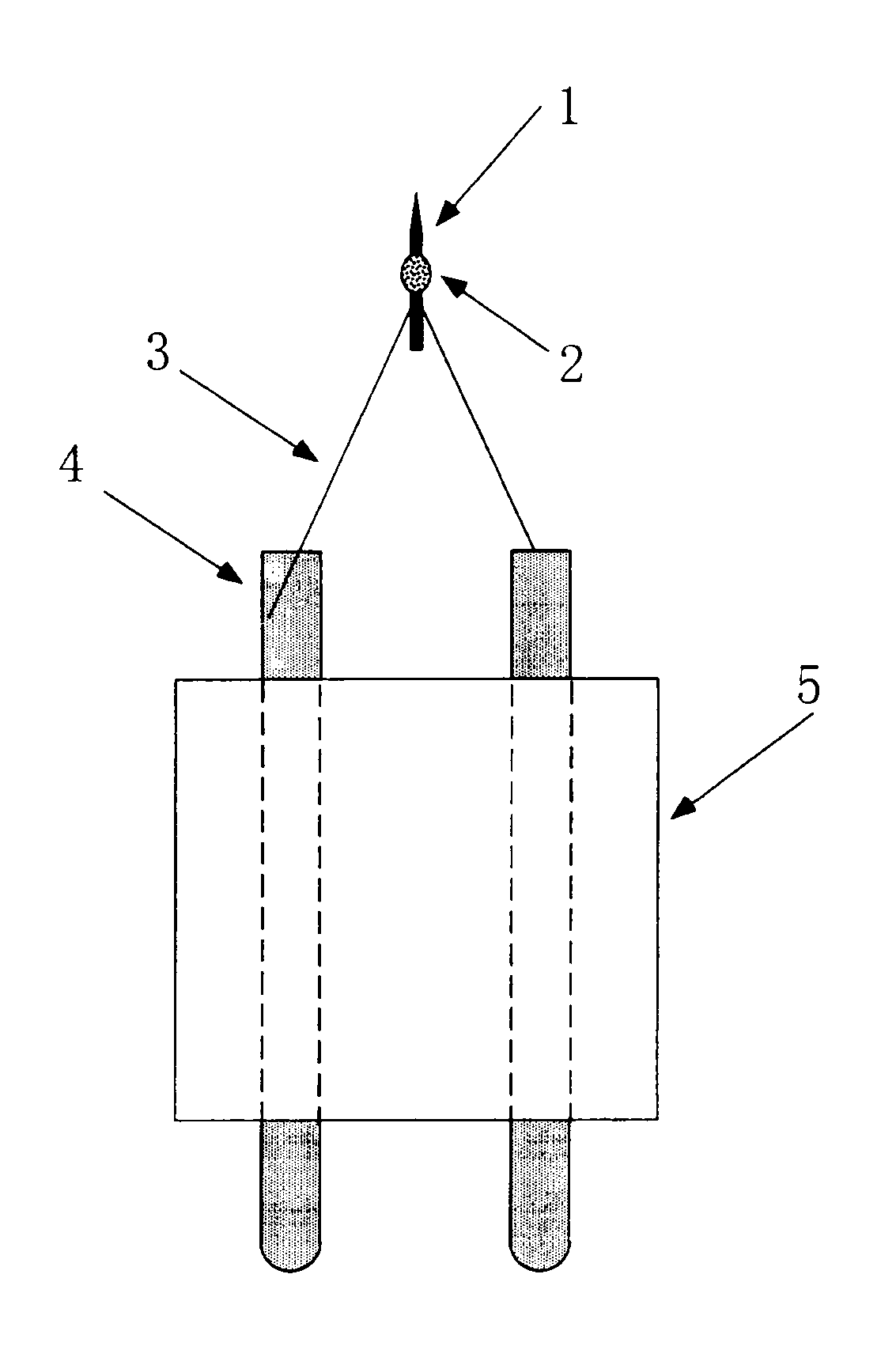
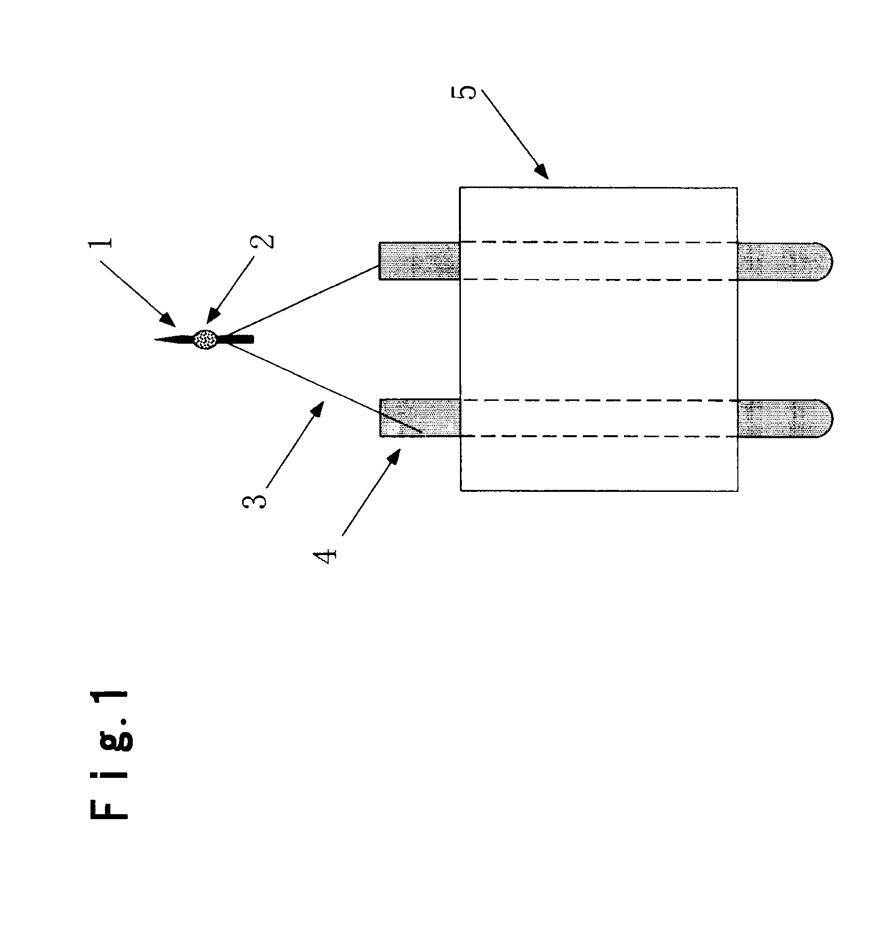
[0081]This single crystal rod 1 is attached by spot welding to a filament 3 made of tungsten attached by welding to a conductive terminal 4 brazed to an insulator 5 (FIG. 1).

[0082]Subsequently, a hydrogened zirconium powder was pulverized in a motor and mixed with an organic solvent to form a slurry, and the slurry is applied to a part of is the single crystal rod 1, and in an oxygen at...


PUM


Abstract

An electron source showing little surplus current even at a time of high angular intensity operation is provided. An electron source comprising an electron emitting portion, a suppressor electrode and an extractor electrode, wherein the electron emitting portion is present at a leading edge of an end of a single crystal rod having a shape comprising a first truncated cone portion or a cone portion, and a second truncated cone portion continuing therefrom. It is preferably the electron source, wherein the single crystal rod has an oxide of a metal element selected from the group consisting of Ca, Sr, Ba, Sc, Y, La, Ti, Zr, Hf and lanthanoide elements as a diffusion source, and the single crystal rod is made of tungsten or molybden of <100> orientation.

Description

TECHNICAL FIELD[0001]The present invention relates to an electron source required to perform high angular intensity operation that is to be used for e.g. an electron beam lithography machine, a wafer inspection apparatus or an electron beam LSI tester.BACKGROUND ART[0002]In recent years, in order to obtain an electron beam having higher brightness and longer operating life than a thermionic cathode, an electron source (hereinafter referred to as a ZrO / W electron source) employing a cathode made of a needle electrode of tungsten single crystal provided with a covering layer comprising zirconium and oxygen, has been used (Non-Patent Document 1).[0003]The ZrO / W electron source is one wherein a diffusing source made of zirconium oxide is provided on a needle cathode of tungsten single crystal having an axial orientation being <100> orientation, so that zirconium and oxygen are diffused to form a covering layer (hereinafter referred to as a “ZrO covering layer”) so as to reduce the...

Claims


Application Information

Patent Timeline
IPC IPC(8): H01J1/46
CPCB82Y10/00B82Y40/00H01J37/065H01J2237/2817H01J37/3174H01J2237/06316H01J2237/065H01J37/28
Inventor TERUI, YOSHINORINAKAHARA, FUMIHIROSAKAWA, SEIICHI
Owner DENKA CO LTD
Why Eureka
Try Eureka