Plasma ashing apparatus and endpoint detection process

a technology of endpoint detection and plasma, which is applied in the direction of photomechanical equipment, semiconductor/solid-state device testing/measurement, instruments, etc., can solve the problems of limiting the overall chip speed, material loss, and increasing the dielectric constan

Inactive Publication Date: 2010-03-04
LAM RES CORP
View PDF64 Cites 35 Cited by
  • Summary
  • Abstract
  • Description
  • Claims
  • Application Information

AI Technical Summary

Problems solved by technology

As integrated devices become smaller, the RC-delay time of signal propagation along interconnects becomes one of the dominant factors limiting overall chip speed.
The ashing step is typically followed by a wet chemical treatment to remove traces of the residue, which can cause further degradation of the low k dielectric, loss of material, and may also cause increase in the dielectric constant.
Although gas mixtures containing one or more of these sources efficiently ash photoresist from the substrate, the use of these gas sources has proven detrimental to substrates containing low k dielectrics.
The increases in dielectric constant affects, among others, interconnect capacitance, which directly impacts device performance.
Moreover, the use of oxygen-containing plasma discharges is generally less preferred for advanced device fabrication employing copper metal layers since copper metal is readily oxidized at the elevated temperatures typically employed for photoresist ashing.
Occasionally, the damage is not detected during metrology inspection of the substrate after plasma processing.
However, the damage can be readily demonstrated by a subsequent wet cleaning process, as may be typically employed after plasma ashing, wherein portions of the carbon and / or hydrogen-containing low k dielectric material are removed.
The removed portions of the dielectric material are a source of variation in the critical dimension (CD) of the feature that is frequently unacceptable and impacts overall device yield.
Moreover, even if a wet clean process is not included, the electrical and mechanical properties of the dielectric material may be changed by exposure to the oxygen-free plasma discharges thereby affecting operating performance.
However, the mechanism of removal is different for these less aggressive plasma discharges.
The buildup of these ashing materials can lead to short mean-time-between-clean (MTBC) times and frequent rebuild / replacement of vacuum hardware resulting in loss of throughput and increased costs of ownership.
Additionally, deposits of photoresist material within the process chamber that are located above the plane of the substrate can lead to particulate contamination on the substrate, thereby further affecting device yields.
An additional problem with oxygen free and nitrogen free plasma discharges is the non-uniformity of the plasma exposure.
Since these plasma discharges are less aggressive, non-uniformity is a significant issue.
However, it has been found that the less aggressive plasma discharges have fewer reactive species and the dispersal from the center point of the baffle plate to its outer edge can result in hot spots on the wafer, i.e., areas of non-uniformity.
Another problem with oxygen free and nitrogen free plasmas concerns endpoint detection.
Traditional endpoint detection methods and apparatus are not suitable for muse with these types of plasma discharges.

Method used


Image

  • Plasma ashing apparatus and endpoint detection process
  • Plasma ashing apparatus and endpoint detection process
  • Plasma ashing apparatus and endpoint detection process

Examples


example 1

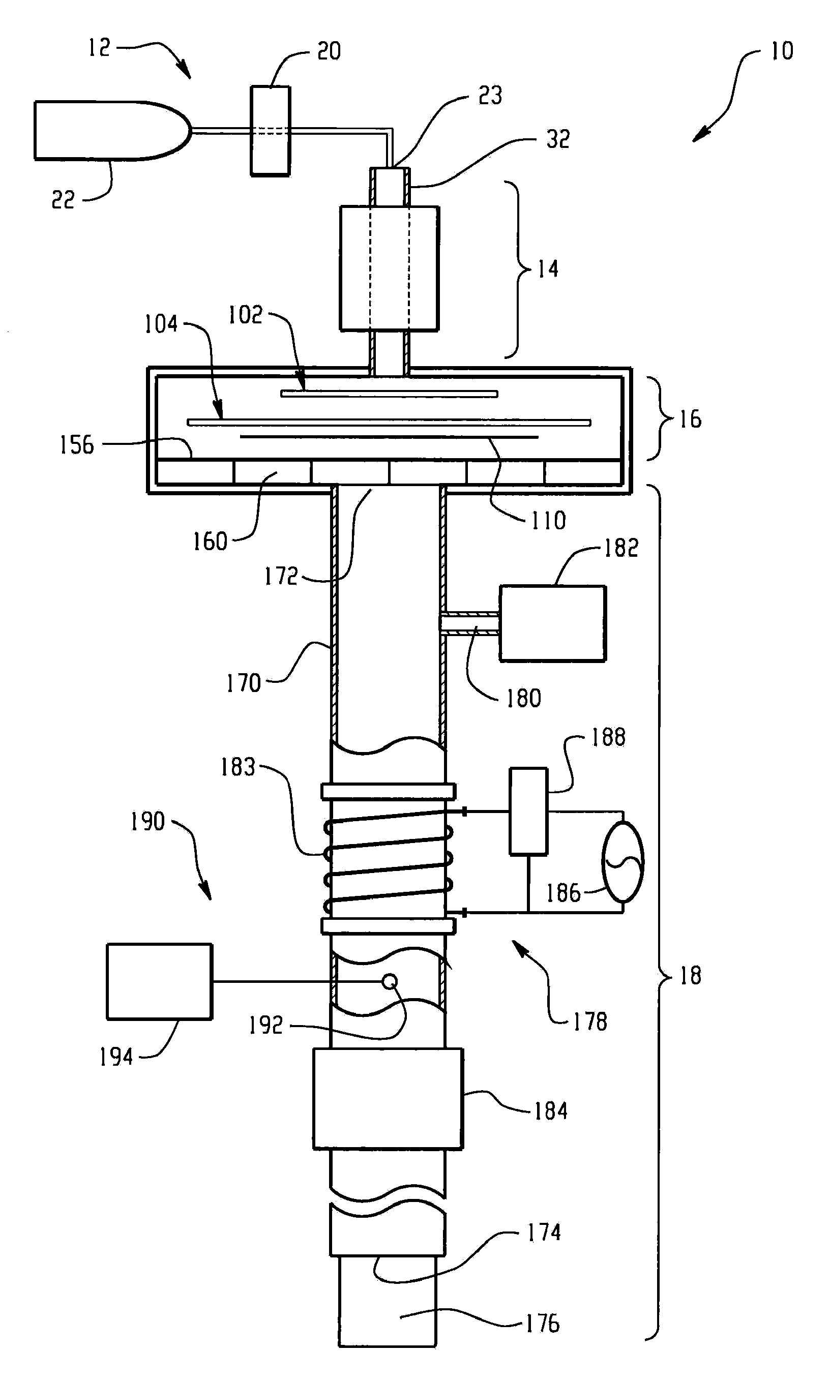
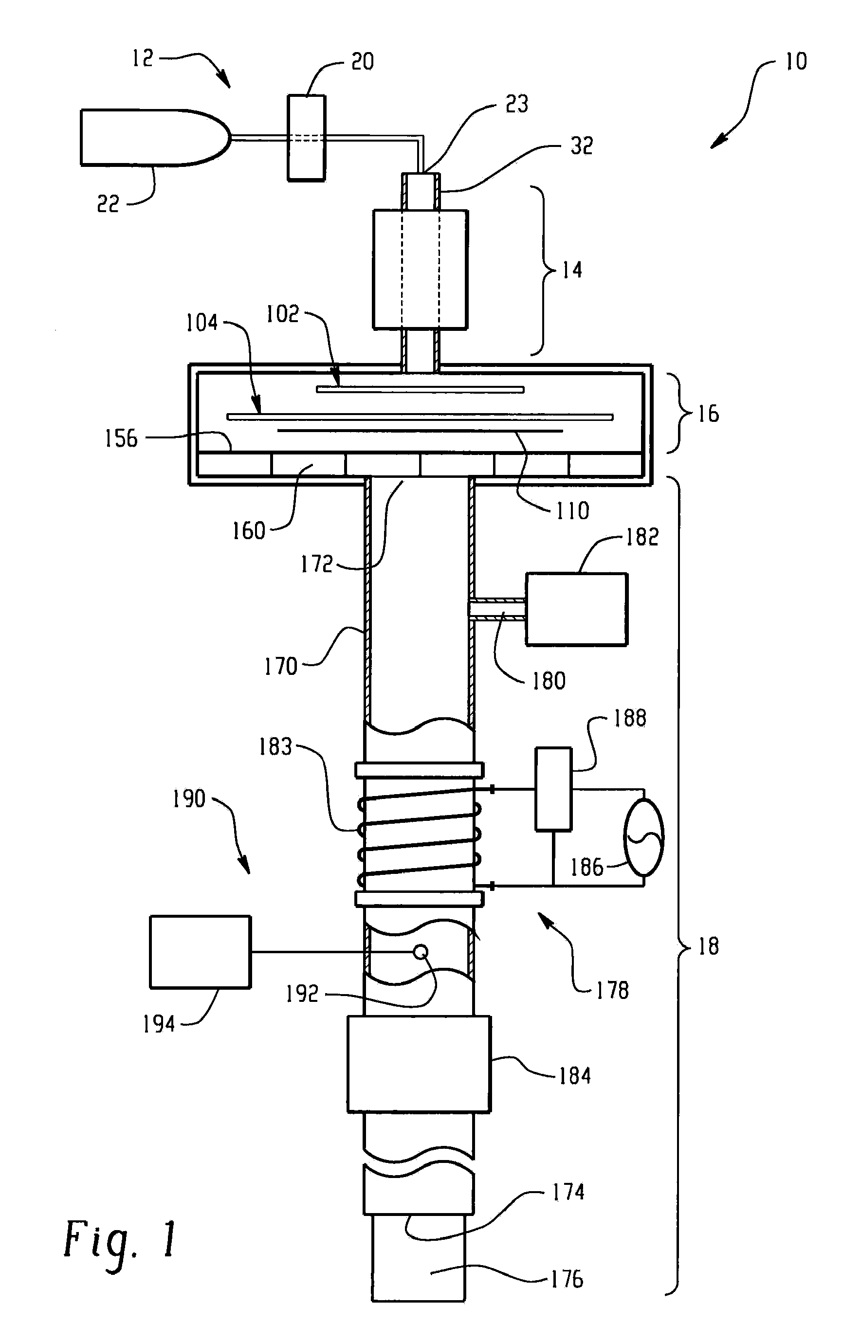
[0082]In this example, optical signals for OH and H were monitored in the exhaust gas conduit downstream from an afterburner in a plasma ashing apparatus as shown in FIG. 1. Helium was introduced into the plasma apparatus at a flow rate of 7,000 sccm and at a pressure of 1.5 torr. A substrate containing photoresist was exposed to heating lamps to slowly heat the wafer to 300° C. and volatilize organic matter from the wafer surface. No plasma was created in the process chamber at this time. During operation of the afterburner at an RF power of 500 W, oxygen gas was introduced into the exhaust conduit at a flow rate of 1,000 sccm. No oxygen was introduced into the process chamber. The optical signals for OH and H were monitored in the exhaust conduit over a period of time to determine endpoint of the plasma ashing process in the process chamber. FIG. 9 graphically illustrates light intensity for these optical signals as a function of time. It was observed that as the organics sublimed...

example 2

[0083]In this example, CO2 was monitored in an exhaust conduit of a plasma asher apparatus as shown in FIG. 1. CO2 was monitored by a residual gas analyzer with and without plasma formed by an afterburner disposed in the exhaust conduit. Similar to Example 1, a resist coated wafer was slowly heated to 300° C. in the process chamber without exposure to plasma. Helium was introduced into the plasma apparatus at a flow rate of 7,000 sccm and at a pressure of 1.5 torr. During operation of the afterburner at an RF power of 300 W, oxygen gas was introduced into the exhaust conduit at a flow rate of 1,000 sccm. No oxygen was introduced into the process chamber. FIG. 10 graphically illustrates CO2 generation as a function of time resulting from generating plasma in the exhaust conduit. If the afterburner was not used, no detectable CO emission would result. However, exposing the organics from the process chamber to the afterburner resulted in strong emission of CO It is noted that within th...

example 3

[0084]In this example, dilution tests were performed to determine the minimum upstream helium flow rates to prevent backstreaming of the oxygen gas into the process chamber. Oxygen was flowed at a rate of 1,000 sccm into the exhaust conduit. A helium gas was flowed into the plasma apparatus initially at a flow rate of 7,000 sccm and was stepwise decreased. Residual gas analysis was taken upstream of the afterburner to monitor partial pressures of helium, nitrogen, and oxygen. FIG. 11 graphically illustrates partial pressures of helium, nitrogen and oxygen as a function of time and dilution. At a helium flow rate of about 175 sccm, it is observed that oxygen is backstreaming into the upstream residual gas analyzer, which could potentially be detrimental for plasma ashing carbon-containing low k dielectric.


PUM

PropertyMeasurementUnit
wavelengthsaaaaaaaaaa

Abstract

A plasma ashing apparatus for removing organic matter from a substrate including a low k dielectric, comprising a first gas source; a plasma generating component in fluid communication with the first gas source; a process chamber in fluid communication with the plasma generating component; an exhaust conduit in fluid communication with the process chamber; wherein the exhaust conduit comprises an inlet for a second gas source and an afterburner assembly coupled to the exhaust conduit, wherein the inlet is disposed intermediate to the process chamber and an afterburner assembly, and wherein the afterburner assembly comprises means for generating a plasma within the exhaust conduit with or without introduction of a gas from the second gas source; and an optical emission spectroscopy device coupled to the exhaust conduit comprising collection optics focused within a plasma discharge region of the afterburner assembly. An endpoint detection process for an oxygen free and nitrogen free plasma process comprises monitoring an optical emission signal of an afterburner excited species in an exhaust conduit of the plasma asher apparatus. The process and apparatus can be used with carbon and / or hydrogen containing low k dielectric materials.

Description

CROSS REFERENCE TO RELATED APPLICATIONS[0001]This application is a divisional of the legally related U.S. Non-Provisional application Ser. No. 10 / 249,964, filed May 22, 2003, which is fully incorporated herein by reference.BACKGROUND[0002]The present disclosure relates to semiconductor apparatuses and processes, and more particularly, to plasma mediated processes and plasma apparatuses suitable for ashing organic material from a substrate including a low k dielectric material.[0003]Recently, much attention has been focused on developing low k dielectric thin films for use in the next generation of microelectronics. As integrated devices become smaller, the RC-delay time of signal propagation along interconnects becomes one of the dominant factors limiting overall chip speed. With the advent of copper technology, R has been pushed to its practical lowest limit for current state of the art so attention must be focused on reducing C. One way of accomplishing this task is to reduce the ...

Claims


Application Information

Patent Timeline
Patent Type & Authority Applications(United States)
IPC IPC(8): H01L21/66G03F7/42H01J37/32H01L21/00
CPCG03F7/427H01J37/32357H01J37/32834H01L21/67253H01J2237/3342H01L21/67069H01J37/32935
Inventor SRIVASTAVA, ASEEM KUMARSAKTHIVEL, PALANIKUMARANBUCKLEY, THOMAS JAMES
Owner LAM RES CORP
Why Eureka
Try Eureka