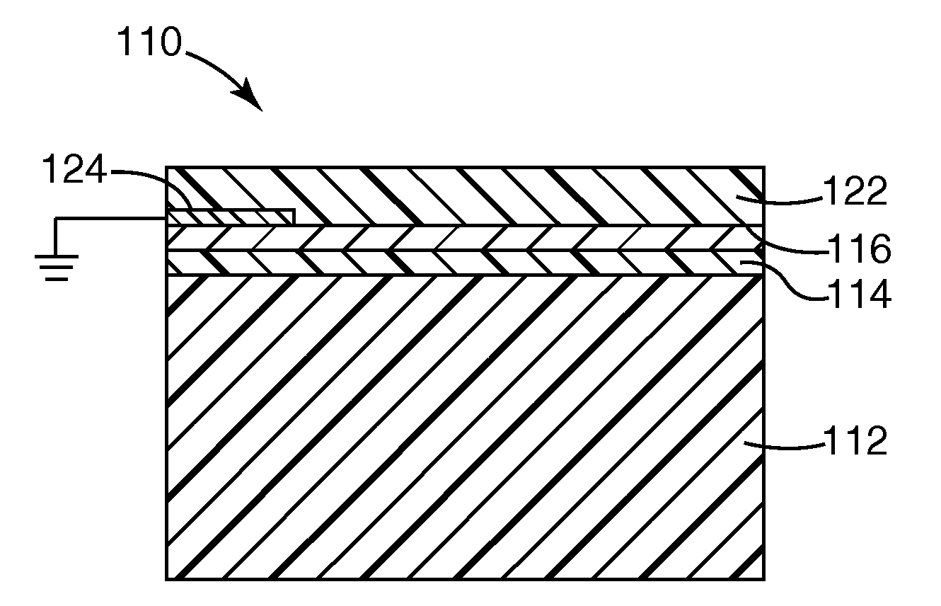
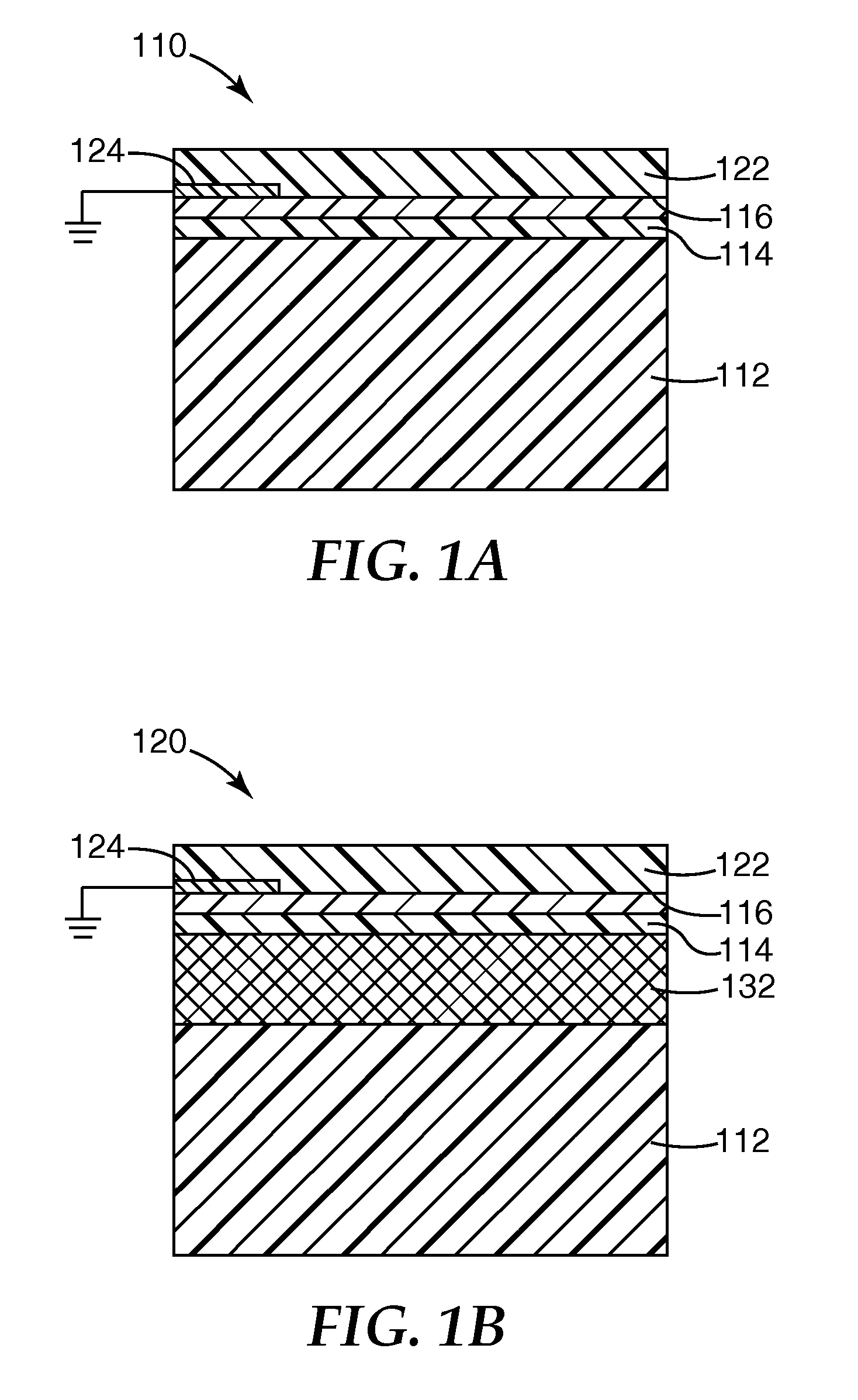
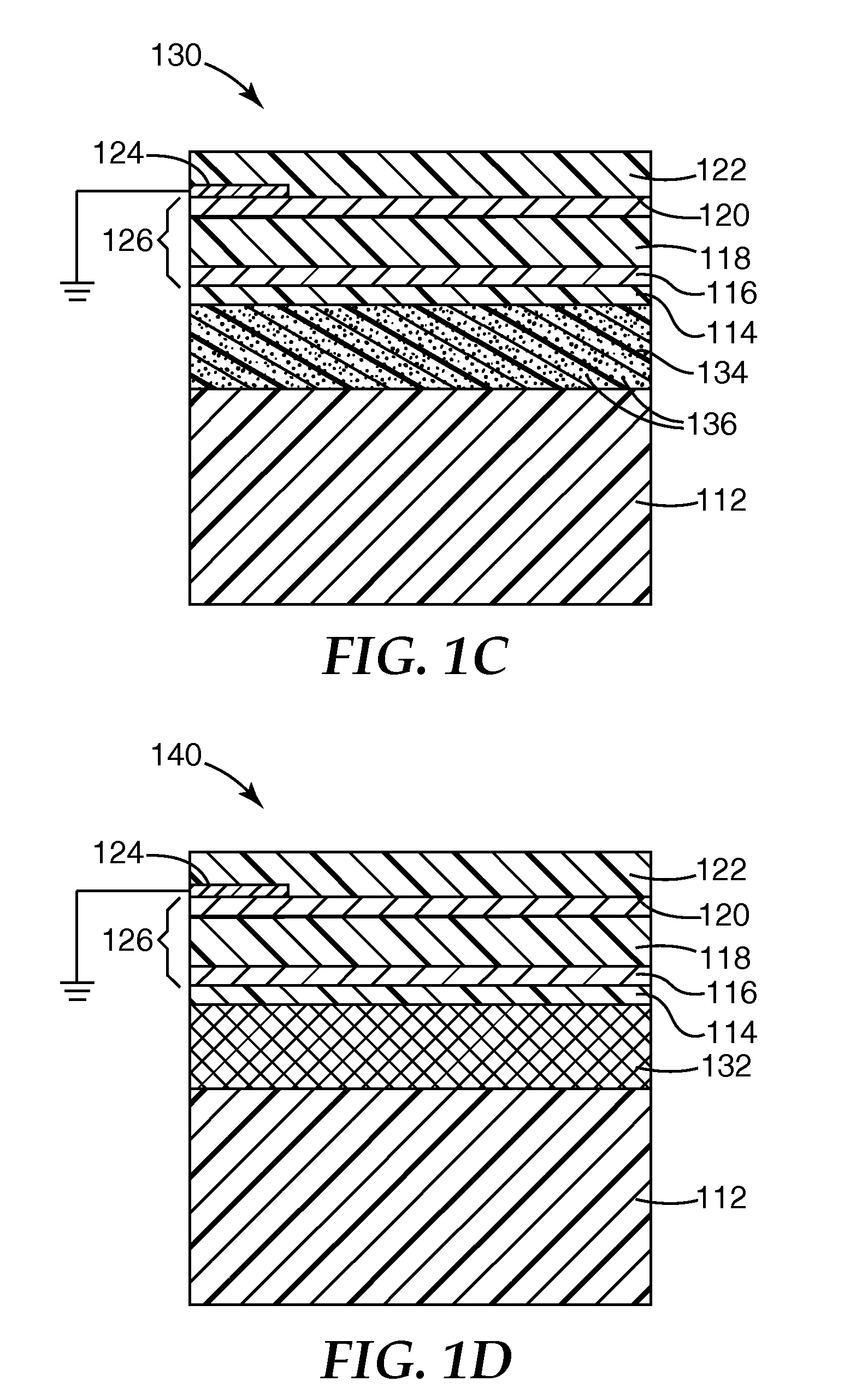
Nucleation layer for thin film metal layer formation
- Summary
- Abstract
- Description
- Claims
- Application Information
AI Technical Summary
Benefits of technology
Problems solved by technology
Method used
Image

Examples
example 1
[0052]A roll of 0.05 mm (2 mil) thick PET substrate was loaded into a roll to roll vacuum chamber like that illustrated in FIG. 2. The substrate was run at a 30.5 m / min (100 ft / min) line speed in the forward direction and coated by reactively magnetron sputtering zinc at 4.0 kW in an atmosphere of 250 sccm of argon and 180 sccm of oxygen, supplied at a pressure of 8.6×10⁻³ Ton. Sequentially, in the same pass, the substrate was magnetron sputtered with silver at 8 kW in an atmosphere of 40 sccm of argon, supplied at 2.8×10⁻⁴ Ton. The film was visible-light transmissive and infrared-reflective, and exhibited 77.1% optical transmission at 550 nm. The electrical properties are shown below in Table 1. Conductivity was measured using a DELCOM™ conductance monitor (Delcom Instruments, Inc.), and sheet resistivity was calculated as the reciprocal of the measured conductivity value. The film had a sheet resistivity of 11.5 Ohms / square.
example 3
[0056]Using the method of Example 1 but with an 18.3 m / min (60 ft / min) line speed and a 98:2 zinc oxide:alumina seed layer sputtering target, a PET substrate was magnetron sputtered with a zinc oxide:alumina nucleating seed layer at 1, 4 and 8 kW, then magnetron sputtered with silver at 2, 3, 4, 5, 6, 8 and 10 kW. The optical properties of the resulting films are shown in FIG. 4, with the curves A, B and C respectively corresponding to the 1, 4 and 8 kW seed layer power levels, and the points along each individual curve corresponding to increasing silver power levels. Higher silver power levels (and for many runs, higher seed power levels) corresponded to lower transmission levels.
example 4
[0057]A PET support was coated with an optical stack containing in order a crosslinked acrylate base coat layer, a first zinc oxide nucleating seed layer, a first silver metal layer, a crosslinked acrylate spacing layer, a second zinc oxide nucleating seed layer, a second silver metal layer and a crosslinked acrylate protective layer in an acrylate / ZnO / Ag / acrylate / ZnO / Ag / acrylate stack configuration. The crosslinked acrylate layers were all made using a mixture of 64% IRR214 acrylate (UCB Chemicals), 28% n-lauryl acrylate and 8% ethylene glycol bis-thioglycolate and applied using the general method of U.S. Pat. No. 6,818,291 B2. The zinc oxide and silver layers were applied using the general method of Example 1. A transmission / reflection curve for the resulting film is shown in FIG. 5. In a comparative run, a similar film was prepared using a titanium oxide seed layer applied using the general method of Comparative Example 2. A transmission / reflection curve for the resulting film is...
PUM
| Property | Measurement | Unit |
|---|---|---|
| Thickness | aaaaa | aaaaa |
| Thickness | aaaaa | aaaaa |
| Transmittivity | aaaaa | aaaaa |
Abstract
Description
Claims
Application Information
 - Generate Ideas
- Intellectual Property
- Life Sciences
- Materials
- Tech Scout
- Unparalleled Data Quality
- Higher Quality Content
- 60% Fewer Hallucinations
Browse by: Latest US Patents, China's latest patents, Technical Efficacy Thesaurus, Application Domain, Technology Topic, Popular Technical Reports.
© 2025 PatSnap. All rights reserved.Legal|Privacy policy|Modern Slavery Act Transparency Statement|Sitemap|About US| Contact US: help@patsnap.com