Laser activated micro accelerator platform

Inactive Publication Date: 2010-04-15
RGT UNIV OF CALIFORNIA
View PDF11 Cites 12 Cited by
  • Summary
  • Abstract
  • Description
  • Claims
  • Application Information

AI Technical Summary

Benefits of technology

[0022]Brachytherapy is not limited to any single medical purpose or procedure. Several different forms of this therapy can be used for treatment of superficial tumors and cancers of accessible organs such as the prostate, cervix, breast, head and neck, and lungs. In a related application, a tumor bed can be irradiated immediately following surgical removal of the tumor (interoperative radiation therapy, or IORT). Brachytherapy has also been used during the installation of arterial stents during the treatment of coronary artery disease, where it can prevent the re-closing of the blood vessel around the stent without the use of drugs.
[0024]According to one aspect of the invention, a radiation source is provided that has an evacuated housing containing a micro-accelerator platform assembly with a pair of dielectric slabs separated by a vacuum gap, each slab having at reflective layer on a side opposite said gap, with at least one reflective layer having a plurality of periodic slots and an active surface. An optical source adapted to directing beams of light to the reflective layers of the dielectric slabs and a source of electrons configured to emit electrons within said vacuum gap and accelerated.

Problems solved by technology

Although certain types of cancer can be treated successfully with current methods, cancer remains a major disease and continues to be a leading cause of death.
However, external ionizing radiation sources deliver undesirable radiation doses to surrounding healthy tissues because the beams must be directed through large sections of healthy organs and tissues to reach the target tissues.
Secondary damage skin, bones, internal organs and other healthy tissues is a significant undesirable side effect from radiation therapy.
Therefore, the challenge of external radiation therapy is to maximize the delivery of a therapeutic radiation dose to the target tumor tissue while minimizing the radiation exposure to healthy surrounding tissues.
First, implanted radioactive sources will continue to emit ionizing radiation, often beyond the life of the patient, and create a risk of damage to healthy tissue over a time.
Physicians and other hospital staff that handle the radioactive materials may be exposed to ionizing radiation over time.
There is also the further administrative burden associated with obtaining, maintaining, and disposing of radioactive materials.
Therefore, implanted radioactive materials are undesirable because they cannot be turned off and on, are complicated to use, and must be well shielded and controlled for safe operation.
Miniature x-ray tubes avoid the issues surrounding radioactive materials, but are limited to a very specific energy range (10-50 kV), and do not have the ability to select or collimate the beam that is produced.
Although these devices are miniaturized, the x-ray tubes still measure several millimeters in each direction and (because of the need for voltage isolation) must be mounted in a rigid and thick support rather than on a narrow catheter limiting its usefulness.
Another problem observed with miniature x-ray tube generators is the generation of excessive heat by the anode of the tube.
Excessive heat may also damage surrounding healthy tissues or blood vessels.
However, these designs still require the creation of large voltages within the body to activate the device and are bulky.
However, there is a large loss in radiation intensity due to the reflections making longer exposure times with minimal therapeutic radiation exposure.

Method used


Image

  • Laser activated micro accelerator platform
  • Laser activated micro accelerator platform
  • Laser activated micro accelerator platform

Examples


example 1

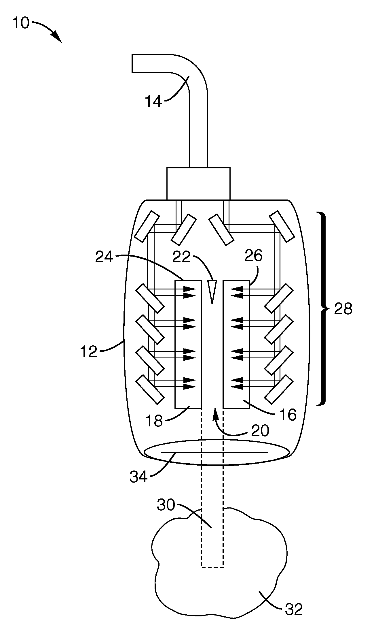
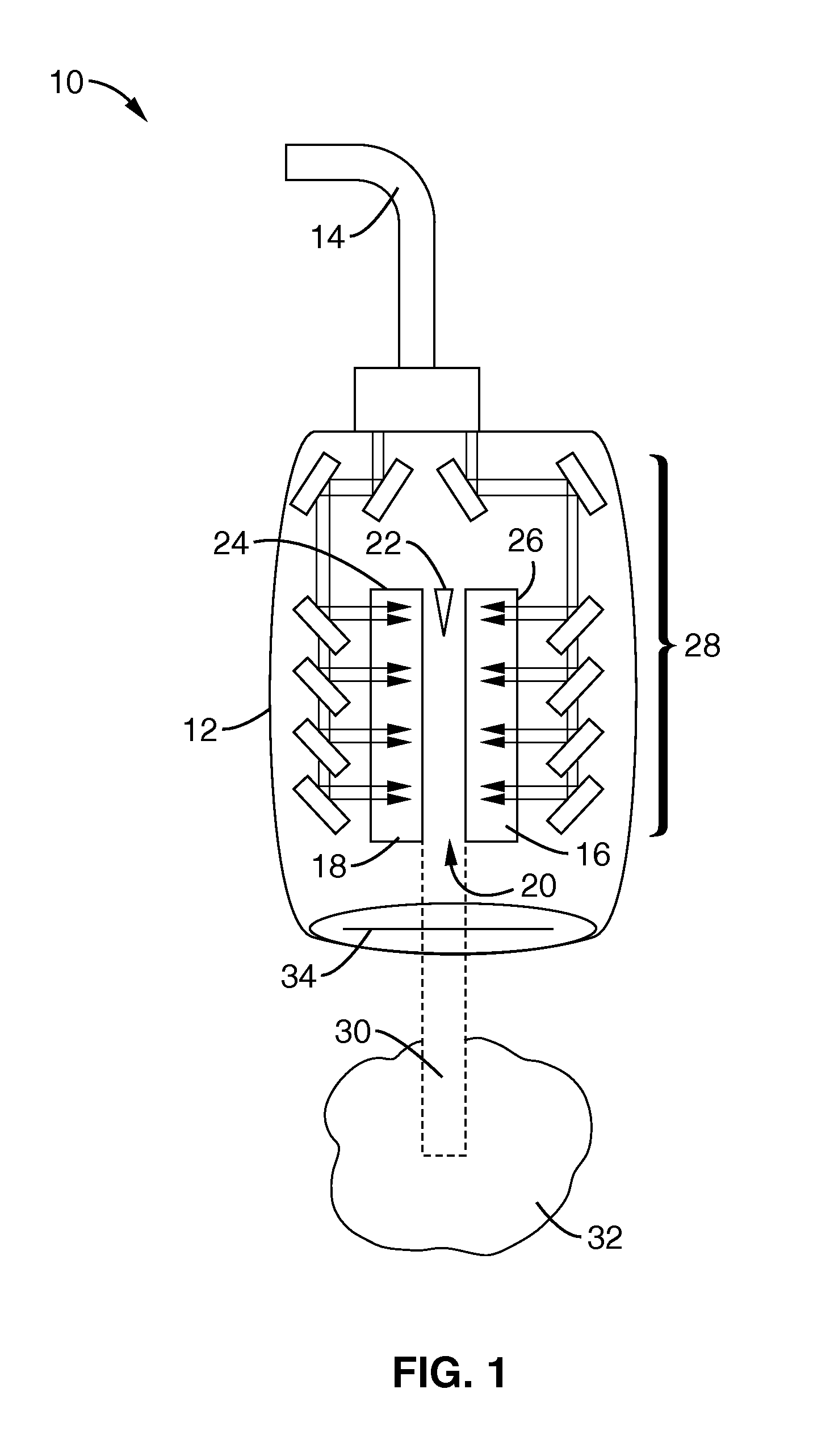
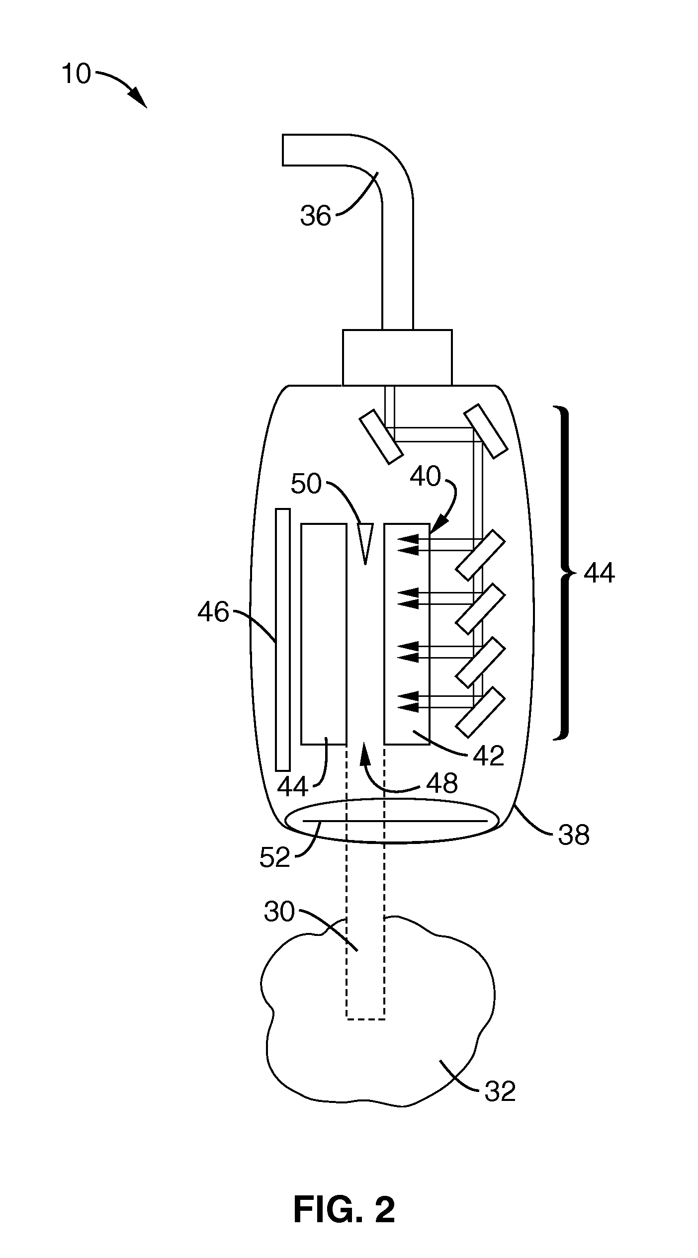
[0082]To demonstrate the function of the microscale particle accelerator, a resonant laser powered structure measuring 1 mm or less in every dimension that is capable of generating and accelerating electron beams at 1-2 MeV energies was evaluated. The accelerator structure had a pair of parallel dielectric slabs separated by a narrow vacuum gap and bounded above and below by a reflective layer or layers. The slabs had a total length of 1 mm and had approximately 1600 structure periods. Periodic slots in the reflector were used to provide a means for coupling radiation into the gap and also to enforce longitudinal periodicity in the structure fields. The dimensions (vacuum gap and dielectric thickness) of the structure were selected so that the structure would be resonant at the laser frequency so that the field pattern would be dominated by a longitudinal standing wave with phase velocity (c). The accelerating field was shown to be typically 4 to 10 times larger than the incident la...


PUM


Abstract

A resonant laser powered micro accelerator platform capable of producing relativistic or near relativistic electrons and, optionally, x-rays. The apparatus has a pair of parallel slab-symmetric dielectric slabs that are separated by a narrow vacuum gap that is preferably tapered. The slabs have a top surface with reflective layers with many periodic slots creating longitudinal periodicity in the structure fields when laser light is directed on the reflectors in one embodiment. Electrons introduced into the gap are accelerated along the length of the slabs. The reflective surface of the slabs is preferably a laminate of alternating layers of high index and low index of refraction materials.

Description

CROSS-REFERENCE TO RELATED APPLICATIONS[0001]This application claims priority from, and is a 35 U.S.C. §111(a) continuation of, PCT international application serial number PCT / US2008 / 059478, filed on Apr. 4, 2008, incorporated herein by reference in its entirety, which claims priority from U.S. provisional application Ser. No. 60 / 910,090 filed on Apr. 4, 2007, incorporated herein by reference in its entirety.[0002]This application is also related to PCT International Publication No. WO 2008 / 156896 published on Dec. 24, 2008 and republished on Feb. 19, 2009, incorporated herein by reference in its entirety.STATEMENT REGARDING FEDERALLY SPONSORED RESEARCH OR DEVELOPMENT[0003]This invention was made with Government support under Grant No. DE-FG02-92ER40693, awarded by the Department of Energy. The Government has certain rights in this invention.INCORPORATION-BY-REFERENCE OF MATERIAL SUBMITTED ON A COMPACT DISC[0004]Not ApplicableBACKGROUND OF THE INVENTION[0005]1. Field of the Inventio...

Claims


Application Information

Patent Timeline
IPC IPC(8): A61B18/24H01J35/32H05H7/00
CPCH01J35/14H01J35/32A61N2005/1088H05G2/00H05H15/00H01J2235/164G21K1/06
Inventor TRAVISH, GILYODER, RODNEY B.ROSENZWEIG, JAMES
Owner RGT UNIV OF CALIFORNIA
Why Eureka
Try Eureka