
Stainless stell separator for fuel cell and the manufacturing method thereof

a fuel cell and steel separator technology, applied in the direction of cell components, final product manufacturing, sustainable manufacturing/processing, etc., can solve the problems of high manufacturing cost, low practicability, and inability to use a single unit, so as to reduce manufacturing time and cost, improve corrosion resistance and electrical conductivity, and facilitate quality control

Active Publication Date: 2010-05-27
HYUNDAE STEEL CO LTD
View PDF18 Cites 20 Cited by
  • Summary
  • Abstract
  • Description
  • Claims
  • Application Information

AI Technical Summary

Benefits of technology

[0025]According to the present invention, the stainless steel separator can be improved in corrosion resistance and electrical conductivity by dipping a commercial stainless steel sheet into an acid aqueous solution for etching, thereby enabling reduction in manufacturing time and cost, and may have a passive film, of which components can be controlled simply by adjusting a mixing ratio of the solution and a dipping time, thereby enabling easy quality control of the separator.
[0026]Further, according to the invention, since the method for surface treatment of the stainless steel separator is performed in such a fashion of stamping a stainless steel sheet, degreasing the stamped stainless steel sheet, and dipping the degreased stainless steel sheet into an acid aqueous solution to achieve desired properties for the stainless steel separator for fuel cells, the stainless steel separator can be produced in a reduced manufacturing period by a continuous process, and since the stainless steel separator can be made of an existing commercial stainless steel sheet, it is easy to secure materials for the stainless steel separator.
[0027]Further, according to the invention, the method for surface treatment of the stainless steel separator uses an alkali solution for degreasing the stainless steel sheet so that the acid solution used for etching can be neutralized by mixing with the alkali solution used for degreasing, allowing easy treatment of waste solution.
[0028]Further, according to the invention, the method for surface treatment of the stainless steel separator ensures that elution of metal ions from the stainless steel separator is suppressed as much as possible during operation of the fuel cell, which suppresses contamination of an electrolyte thin membrane and thereby ensures an excellent long-term performance of the fuel cell.
[0029]Further, according to the present invention, the method for surface treatment of the stainless steel separator for the fuel cell ensures the stainless steel separator can fulfill the requirement for physical properties simply with the etching process without a commercial coating process, thereby enabling reduction in manufacturing cost and time.

Problems solved by technology

Since it is impractical to use only a single unit cell of the fuel cell due to its low voltage, a stack of several to several hundred unit cells is generally used in practice.
Irrespective of improvement in corrosion resistance and electrical conductivity, such techniques as described above suffer from high manufacturing costs and generation of defects such as pin holes, which leads to low practicability.
However, these techniques have problems in that there is a high possibility of corrosion related to pin holes caused by hydrogen generated during the gold coating, and that although gold is thinly coated thereon, it is still expensive compared to other wet coating.
However, carbon spread into the passive film couples with chrome existing in a large amount in the passive film to precipitate chrome carbide, thereby reducing the content of chrome.
As a result, the corrosion resistance on the surface of the material is deteriorated, providing an adverse influence on performance of the fuel cell.
Further, when such a fuel cell is applied to vehicles, the carbon powder is likely to be detached from the separator due to vibration during operation, and since stainless steel exhibits high contact resistance in the case of no proper pretreatment, it is not suitable to be used as a raw material for the metal separator.
However these prior techniques have difficulty with commercialization due to low productivity resulting from use of expensive Ti material and the vacuum process.
As such, since iron oxides such as FeO, Fe2O3, and Fe3O4 formed on the surface of the stainless steel sheet by coupling of Fe and O cannot suppress corrosion of the separator in a sulfuric acid atmosphere at a high temperature of 80° C. and act as an insulator, the iron oxides lower the electrical conductivity of the separator, thereby causing deterioration in performance of the fuel cell.

Method used

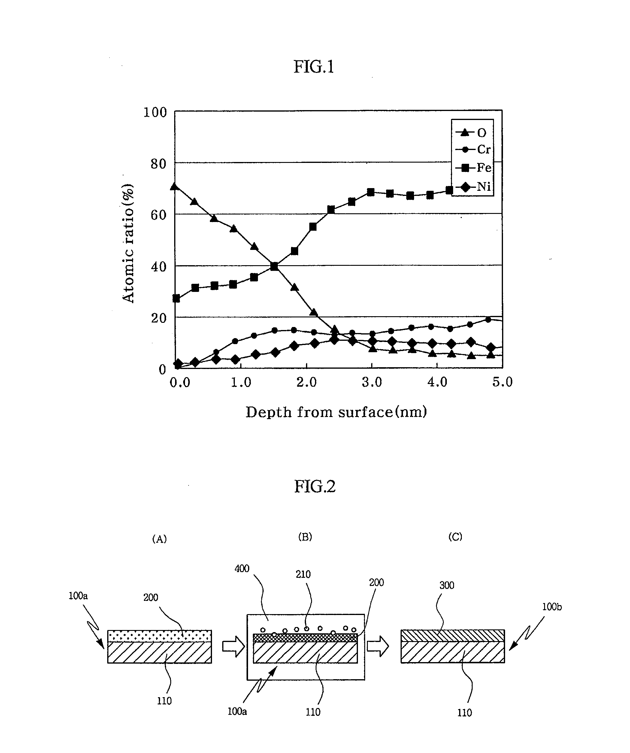

Image

  • Stainless stell separator for fuel cell and the manufacturing method thereof
  • Stainless stell separator for fuel cell and the manufacturing method thereof
  • Stainless stell separator for fuel cell and the manufacturing method thereof

Examples


Embodiment Construction

[0038]According to the present invention, a stainless steel sheet comprises 0.08 wt % carbon (C), 16˜28 wt % chrome (Cr), 0.1˜20 wt % nickel (Ni), 0.1˜6 wt % molybdenum (Mo), 0.1˜5 wt % tungsten (W), 0.1˜2 wt % tin (Sn), 0.1˜2 wt % copper, and the balance of iron (Fe) and other unavoidable impurities.

[0039]The stainless steel sheet is dipped into an etching solution for 30 seconds˜10 minutes to reduce processing time.

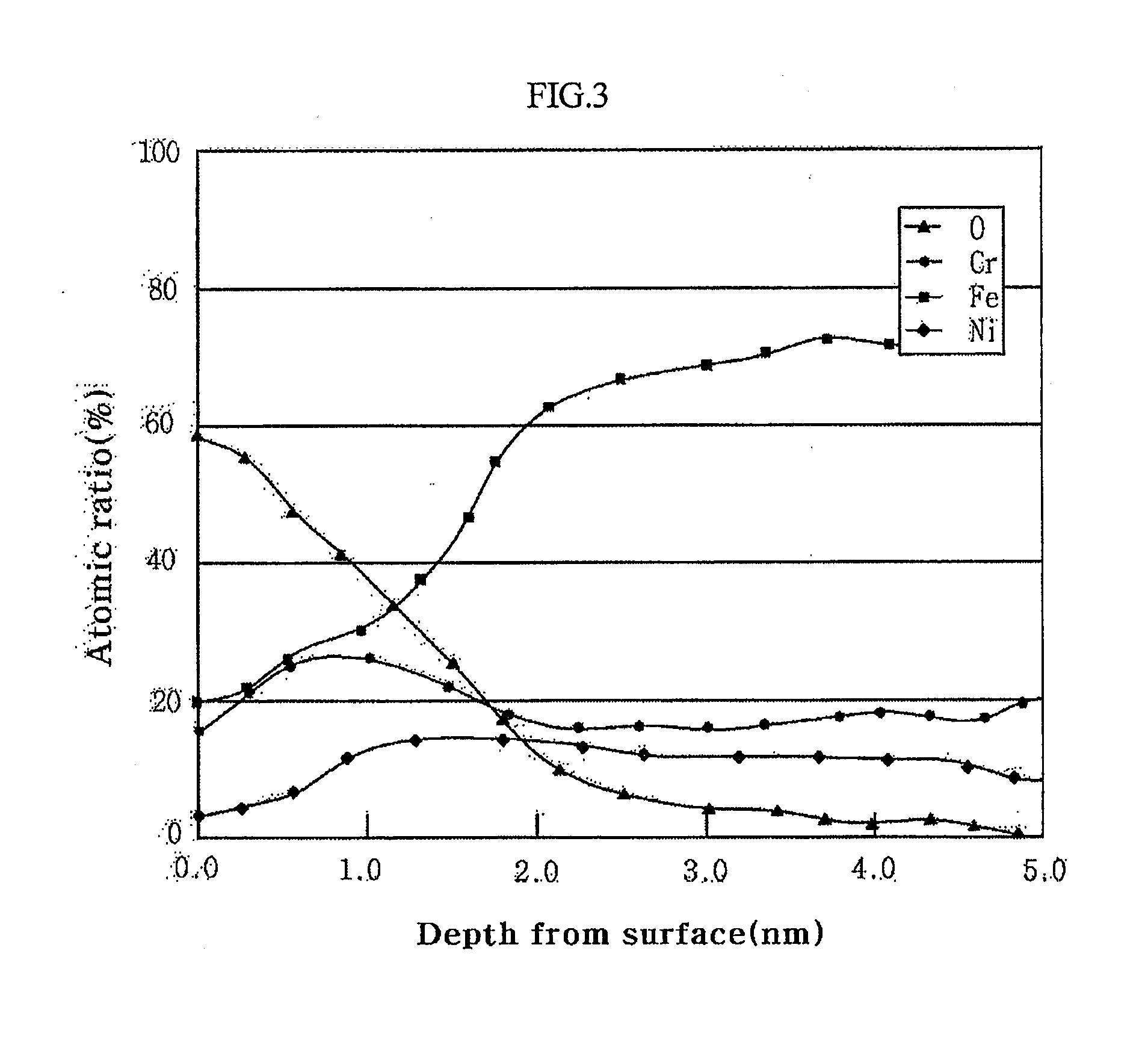
[0040]The stainless steel sheet has a passive film, of which Fe content is decreased by an operation of reducing the content of Fe in the passive film. Here, the passive film comprises 20˜75 wt % chrome (Cr) and 30 wt % or less iron (Fe) while satisfying a condition of (Cr+Ni) / Fe≧1 in terms of atomic weight.

[0041]Hereinafter, embodiments of the present invention will be described in detail with reference to the accompanying drawings.

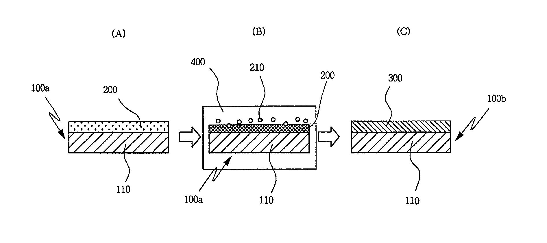
[0042]FIG. 2 is a diagram schematically illustrating a process of manufacturing a stainless steel separator for a fuel cell with an etching...


PUM

PropertyMeasurementUnit
Temperatureaaaaaaaaaa
Timeaaaaaaaaaa
Electric potential / voltageaaaaaaaaaa

Abstract

A method for surface treatment of a stainless steel separator for a fuel cell comprises preparing a stainless steel sheet containing nickel, chrome and iron, and having a passive film on a surface of the stainless steel sheet, and dipping the stainless steel sheet into a mixed etching solution of nitric acid (HNO3) and sulfuric acid (H2SO4) at a temperature of 50-70° C. for 30 seconds to 30 minutes to selectively lower an amount of Fe in the passive film formed on the surface of the stainless steel sheet.

Description

TECHNICAL FIELD[0001]The present invention relates to a stainless steel separator for a fuel cell and a method for surface treatment thereof. More particularly, the present invention relates to a stainless steel separator for a fuel cell, which is subjected to surface treatment for improvement of electrical conductivity and corrosion resistance, and to a method for surface treatment thereof.BACKGROUND ART[0002]A fuel cell is an electrochemical energy conversion device that generally converts chemical energy into electric energy through oxidation and reduction of hydrogen and oxygen.[0003]At an anode, oxidation occurs to split hydrogen into hydrogen ions and electrons. The hydrogen ions are moved to a cathode through an electrolyte, and the electrons are moved to the cathode through a circuit. At the cathode, reduction occurs to combine the hydrogen ions and the electrons with oxygen to produce water.[0004]Since it is impractical to use only a single unit cell of the fuel cell due to...

Claims


Application Information

Patent Timeline
IPC IPC(8): H01M2/16C23F1/16
CPCC22C38/008C22C38/42C22C38/44C23G1/085C23G1/088C23F1/28H01M8/021H01M8/0219H01M8/0228Y02E60/50C25D11/34C25F3/06Y02P70/50C23F1/16
Inventor JEON, YOO TAEKJEONG, YEON SOO
Owner HYUNDAE STEEL CO LTD
Learn More