
Simultaneous warm gas desulfurization and co-shift for improved syngas cleanup

a technology of syngas cleanup and simultaneous warm gas, which is applied in the direction of combustible gas purification/modification, metal/metal-oxide/metal-hydroxide catalyst, bulk chemical production, etc., can solve the problems of inability to achieve steady state operation, significant hurdles that need to be overcome, and failure of large-scale warm desulfurization demonstration units

Active Publication Date: 2010-06-03
UOP LLC
View PDF24 Cites 2 Cited by
  • Summary
  • Abstract
  • Description
  • Claims
  • Application Information

AI Technical Summary

Benefits of technology

[0010]The present invention involves a process for simultaneous desulfurization and gas shift of a gaseous stream comprising contacting the gaseous stream with a nickel aluminate catalyst. The nickel aluminate catalyst is preferably selected from the group consisting of Ni2xAl2O2x+3, Ni(2−y)Ni0yAl2O(5−y), Ni(4−y)Ni0yAl2O(7−y), Ni(6−y)Ni0yAl2O(9−y), and intermediates thereof, wherein x≧0.5 and 0.01≦y≦2. Preferably, x is between 1 and 3. More preferably, the nickel containing compound further comprises Ni2xAl2O2x+3−zSz wherein 0≦z≦2x. The nickel containing compound reacts with more than 10% of sulfur compounds within the gaseous stream. Preferably, the nickel containing compound reacts with more than 50% of the sulfur compounds within the gaseous stream. At least 10% of the carbon monoxide within the gaseous stream is converted to carbon dioxide. The nickel containing compound contacts the gaseous stream at a temperature from about 250° to 550° C. Preferably the temperature is from 400° to 500° C. and the pressure is from about 10 to 80 bar. The GHSV (at STP) is preferably higher than 500 m3 / m3 / hr. Steam and CO are present at a molar ratio from about 0.5:1 to 4:1 and preferably at a molar ratio from about 1.5:1 to 3.5:1.

Problems solved by technology

This could improve greatly the overall process efficiency, however, there are significant hurdles that need to be overcome before such a hot-fuel gas clean-up system is made commercially available.
All large scale warm desulfurization demonstration units have failed mostly due to inappropriate sulfur-scavenger materials.
Steady state operation was not reached in the course of the 42 months demo operation and the Zn-based S-scavenger material failed since it did not hold up physically in the entrained bed reactor.
The hot gas desulfurization unit was an intermittently moving bed of Zn oxide based sorbent that operated at 482° C. The demonstration again failed due to very high attrition loss (which made operation with that particular sorbent far from cost effective) and due to significant reactivity loss because of Zn sulfate formation and Zn volatilization.
In addition to efficiently cooling the raw syngas and recovering part of the sensible heat, significant decontamination takes place in the quenching step.
Unfortunately, these processes require cooling the fuel gas to low temperatures and then subsequently reheating it to temperatures adequate to its downstream use.

Method used


Image

  • Simultaneous warm gas desulfurization and co-shift for improved syngas cleanup

Examples


example 1

[0015]An Ni aluminate material with the final formula Ni4.09Al2O7.09: 2.4H2O was prepared via a Layered Double Hydroxide (LDH) Metal Oxide Solid Solution (MOSS) route. In this procedure, a clear solution was prepared by combining 328.0 g of 50% aqueous NaOH with 1170.0 g DI water, followed by the addition of 136.1 g of NaCO3:H2O. A second solution was prepared by dissolving 345.3 g Ni(NO3)2:6H2O and 217.7 g Al(NO3)3:9H2O into 840.0 g DI water. The aqueous metal nitrate solution was then added to the first solution dropwise while stirring over a 2 hour period. The reaction mixture was heated to 80° C. and held at temperature for 16 to 18 hours while stirring. The solids were then isolated by vacuum filtration and washed vigorously with DI water (26 liters) and dried in ambient air. At this point, XRD confirmed the synthesis of Ni—Al—O Layered Double Hydroxide material which was then calcined (in flowing air) for 6 hours at 450° C. followed by 4 hours at 550° C. to generate the metal ...

example 2

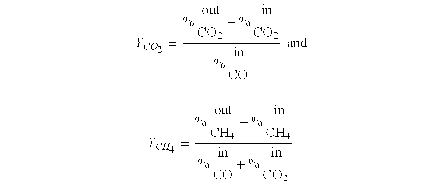
[0016]The sulfidation / CO-shift experiments were done with the Ni4.09Al2O7.09: 2.4 H2O material prepared in Example 1 at atmospheric pressure, 450° C. with a gas simulating an oxygen blown gasifier containing 1.1% H2S+0.0763% COS+45% H2+46% CO+7.2% CO2+0.7% CH4. Steam had been co-fed in a steam:CO molar ratio 3.5:1. The wet basis GHSV was 2100 h−1. The oxidative regeneration was done with 2% O2 in N2 at 500° C. and GHSV=2100 h−1. In the very first cycle, the S absorption capacity before S-breakthrough was 10 wt-% S and the CO conversion was about 95% to both CO2 and CH4. The Ni aluminate generated about 10% CH4 which represents about 60% of the equilibrium methane formation. The sample had been heated to the reaction temperature under a H2 atmosphere, such that some of the Ni present in the Ni aluminate material had been reduced to the metallic state thus creating the active sites for the methanation reaction. After a 500° C. oxidation cycle, when no Ni0 which promotes the methanatio...


PUM

PropertyMeasurementUnit
temperatureaaaaaaaaaa
pressureaaaaaaaaaa

Abstract

The present invention involves a process and materials for simultaneous desulfurization and water gas shift of a gaseous stream comprising contacting the gas stream with a nickel aluminate catalyst. The nickel aluminate catalyst is preferably selected from the group consisting of Ni2xAl2O2x+3, Ni(2−y)Ni0yAl2O(5−y), Ni(4−y)Ni0yAl2O(7−y), Ni(6−y)Ni0yAl2O(9−y), and intermediates thereof, wherein x≧0.5 and 0.01≦y≦2. Preferably, x is between 1 and 3. More preferably, the nickel containing compound further comprises Ni2xAl2O2x+3−zSz wherein 0≦z≦2x.

Description

BACKGROUND OF THE INVENTION[0001]This invention relates to the materials used for and process for both the removal of sulfur compounds from a gaseous stream and for the water gas shift reaction. More specifically, the invention relates to the use of a nickel containing aluminate catalyst to provide for simultaneous desulfurization and water gas shift at temperatures of about 450° C.[0002]The gaseous stream may originate from any partial oxidation or gasification process of a carbon containing feedstock. The gaseous stream may be a fuel gas originating from an IGCC (Integrated Gasification Combined Cycle) coal gasification plant, it may be a flue gas from a fluid catalytic cracking unit (FCC), it may be a synthesis gas (syngas) from steam reforming of natural gas, certain gasification reactions or from gasification of coal. Synthesis gas is the name generally given to a gaseous mixture principally comprising carbon monoxide and hydrogen, but also possibly containing carbon dioxide an...

Claims


Application Information

Patent Timeline
Patent Type & Authority Applications(United States)
IPC IPC(8): C01G53/04C01F7/70
CPCB01D53/8603C10K3/04B01D2257/306B01J23/002B01J23/007B01J23/755B01J35/1019B01J35/1038B01J35/1061C01B3/48C01B2203/0283C01B2203/0415C01B2203/0475C01B2203/0485C01B2203/1058C01G53/00C01P2006/12C01P2006/14C01P2006/16C10J2300/1618C10K1/00B01D2255/20753C01P2002/54Y02P20/52B01J35/633B01J35/647B01J35/615
Inventor SERBAN, MANUELAKING, LISA M.BHATTACHARYYA, ALAKANANDAVANDEN BUSSCHE, KURT M.
Owner UOP LLC
Learn More