[0018]To facilitate elastic deformation of the device, the struts of the support cage can be fabricated from deformable high strength
metal alloys. Nonlimiting examples include
titanium and / or
tantalum, and their various alloys.
Titanium alloys useful in such embodiments include the high strength shape memory alloys, including those comprising
nickel and
titanium (e.g., various members of the class of alloys commercially available as nitinol). Both
titanium and
tantalum alloys have the dual
advantage of high strength and low
magnetic susceptibility, which creates minimal
image artifact in
Magnetic Resonance Imaging (MRI) and
Magnetic Resonance Angiography (MRA). Stainless steel alloys can also be used; however, many such alloys have
magnetic susceptibility due to the presence of iron,
chromium, etc., which contributes to
image artifact in MRI and MRA. Those alloys might still be used where MRI and / or MRA are not contemplated; or resort may be had to commercially available “non-magnetic” stainless steels that produce little or no MRI / MRA image artifact. Other flexible
metal alloys such as blue tempered and polished steel (also known as
clock spring steel) having a carbon content of between about 0.90 to 1.04 percent and a Rockwell
hardness of about C48 to C51.
[0020]The support cage must also be fabricated to
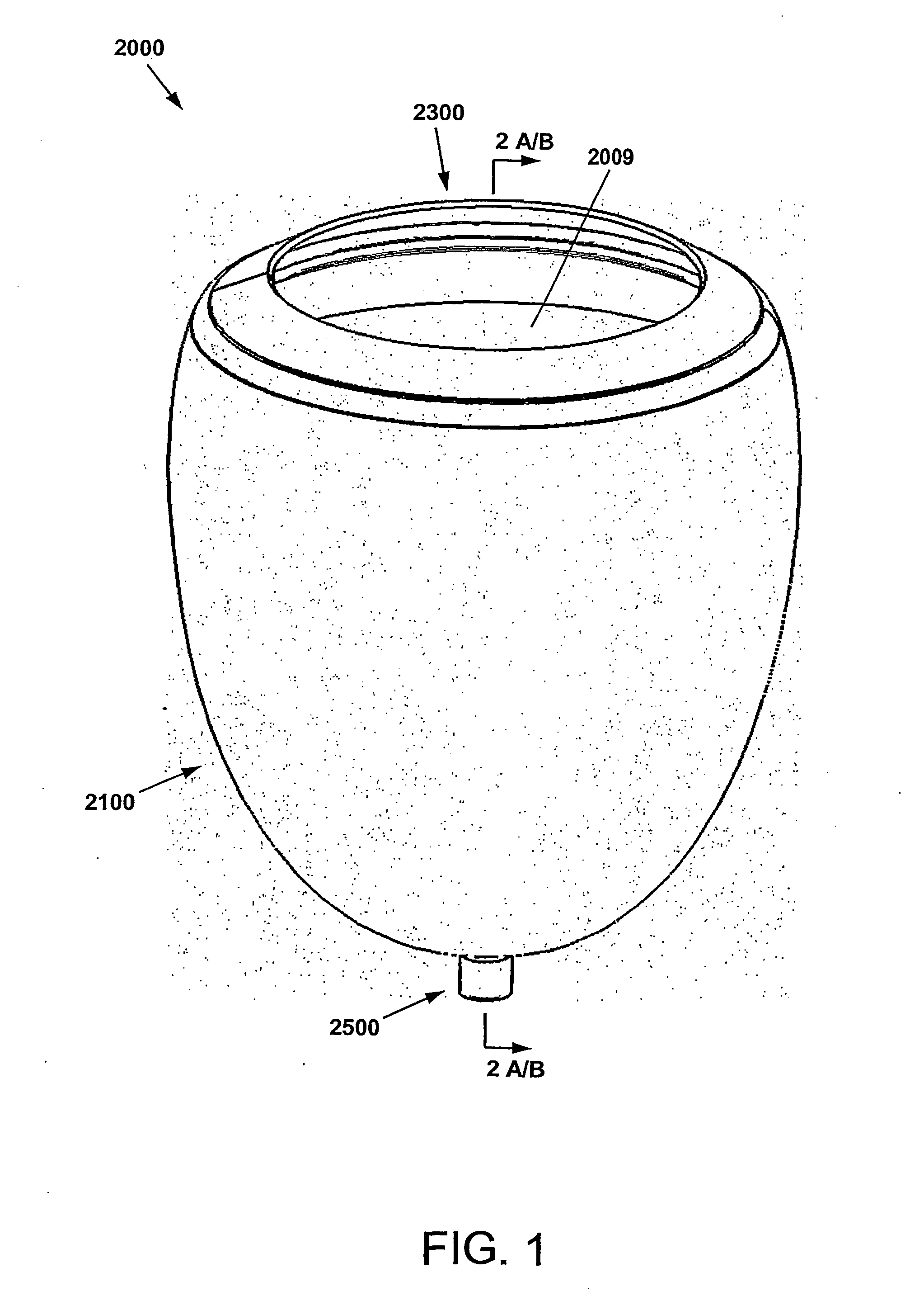
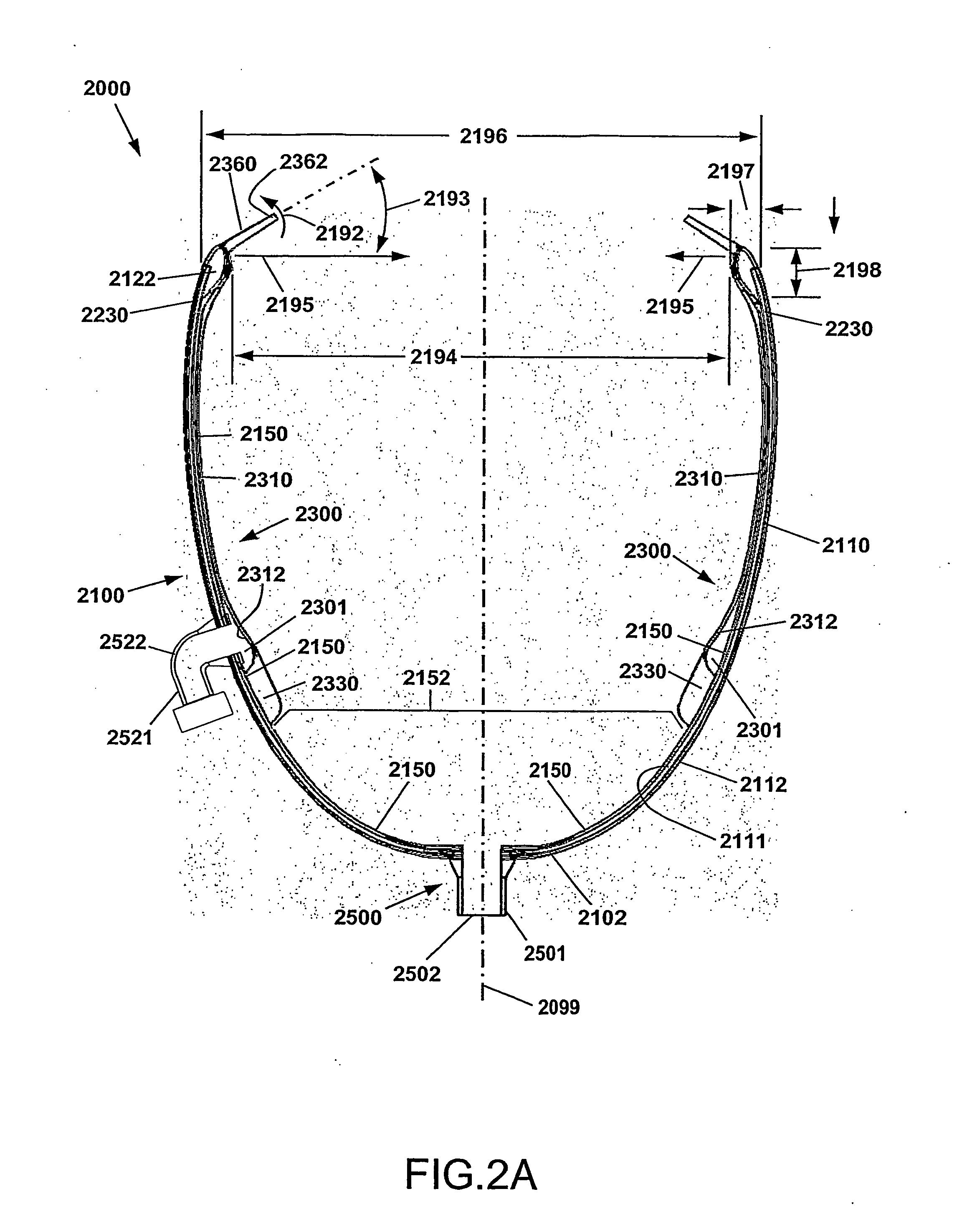
resist significant collapsing during diastolic assistance to the heart. When vacuum is applied to the elastic liner of the device to provide diastolic assistance, the support cage prevents inward flexing of the cup-shaped shell. Since the internal volume of the device is thus maintained during vacuum application, the elastic liner is pulled outwardly toward the wall of the cup shaped shell, thereby pulling outwardly on the walls of the heart ventricles and providing diastolic assistance.
[0021]The
polymer-
fiber composite of the cup-shaped shell must also be collapsible, but selected and constructed such that it provides little or substantially no resistance to collapsing of the device for placement in a deployment tube. In contrast, when the support cage is fully open and the device is deployed on a heart, the cup-shaped shell prevents any significant expansion of the internal volume of the device. The
polymer fiber composite that forms the shell must be flexible such that the shell can be folded when the device is collapsed, but also inelastic when placed under tension, so that the internal volume is constrained when the device is assisting a heart. In particular, during systolic assistance to a heart, when
fluid pressure is applied to the elastic liner of the device, the
polymer fiber composite is in tension and prevents an increase in the internal volume of the device. Since the cup shell internal volume cannot increase, the elastic liner is forced to deform and stretch inwardly, thereby displacing the walls of the heart ventricles and providing systolic assistance.
[0028]The DMVA device described above is advantageous because it precisely drives the mechanical actuation of the ventricular chambers of the heart without damaging the tissue thereof, or the circulating blood; while being installed by a simple minimally
invasive procedure that can be quickly performed. Embodiments of the DMVA device may monitor and provide functional performance and / or image data of the heart; and / or electrophysiological
monitoring and control of the heart, including pacing and
cardioversion-
defibrillation electrical signals to help regulate and / or synchronize device operation with the native electrical
rhythm and / or contractions thereof. As a result, a greater variety of patients with cardiac
disease can be provided with critical life-supporting care in a minimally invasive manner, under a greater variety of circumstances, including but not limited to,
resuscitation, bridging to other therapies, and extended or even permanent support.
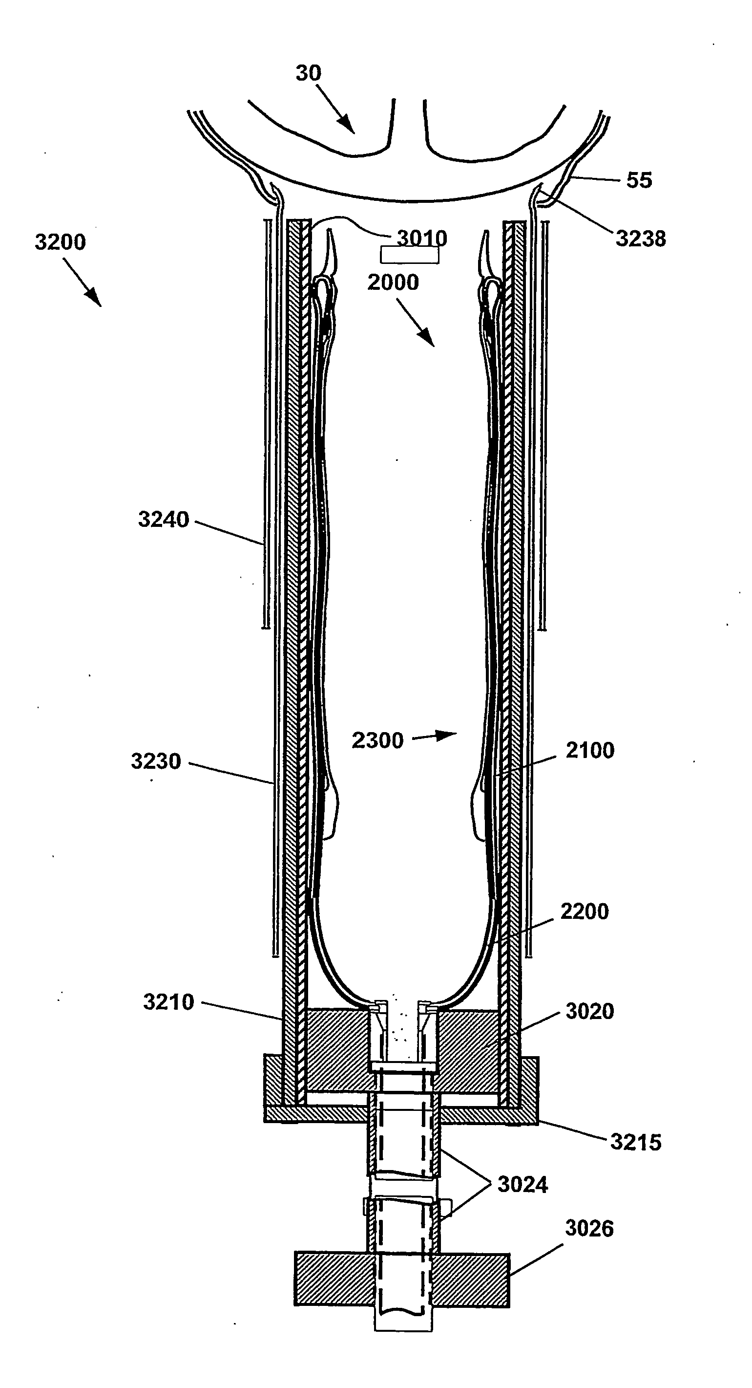
[0029]Also provided is a method of deploying a minimally invasive DMVA. In one method, the shell is collapsed from an open cup-shape to a compact configuration that is collapsed along the shell's longitudinal axis. In one embodiment, the shell is introduced via a deployment tool, which may be a flexible or rigid hollow structure compatible with the longitudinally collapsed shell, e.g., tubular. A modest sized incision may then be made
proximate the heart. In one embodiment, the incision is made in the chest, and may be positioned to facilitate
insertion of the deployment tool between the ribs or below the
rib cage. The deployment tool is inserted into the incision, whereupon the collapsed shell is displaced from the deployment tool. Upon displacement, the collapsed shell resumes its open, or cup-shaped, configuration. In one embodiment, the interior of the cup-shaped shell complements the shape of the heart requiring assistance. The open cup-shaped shell is then positioned over the heart. The DMVA is then positioned to assist the function of the heart, by structurally supporting systolic and / or diastolic action, and / or by regulating the timing thereof.
[0030]The DMVA device can support the heart through a period of
acute injury and allow healing that potentially results in substantially a
full recovery of unsupported heart function.