Fuel cell

a fuel cell and direct oxidation technology, applied in the direction of fuel cells, solid electrolyte fuel cells, cell components, etc., can solve the problems of reducing the potential at the cathode, deteriorating the utilization efficiency of fuel, and reducing the power generation voltage, so as to prevent the leakage of fuel, increase the amount of mco, and reduce the catalytic activity

Inactive Publication Date: 2010-07-29
PANASONIC CORP
View PDF12 Cites 16 Cited by
  • Summary
  • Abstract
  • Description
  • Claims
  • Application Information

AI Technical Summary

Benefits of technology

[0012]However, due to the structural problem of MEAs, there is a portion where the methanol concentration in the anode-side surface of the polymer electrolyte membrane is not smaller than the methanol concentration in the fuel flow channel. The anode and cathode are normally surrounded by a gasket for preventing the leakage of fuel and air; however, in actual production process, it is difficult to completely seal the end surfaces of the anode and cathode with the gasket with no clearance formed therebetween. As such, a clearance is present more or less between the end surfaces of the anode and cathode and the gasket, creating a region between the anode porous substrate receiving the supply of fuel from the fuel flow channel and the polymer electrolyte membrane, the region in which neither the anode catalyst layer nor the anode water-repellent layer is present. Due to the presence of this region, part of the methanol supplied from the fuel flow channel reaches the polymer electrolyte membrane with its concentration being maintained, and permeates through the interior thereof. As a result, the concentration gradient of methanol in the anode-side surface and the cathode-side surface of the polymer electrolyte membrane increases, resulting in a local increase of the amount of MCO.
[0013]On the other hand, by applying the production method disclosed in Japanese Laid-Open Patent Publication No. 2003-203646, it is possible to prevent a high concentration fuel (e.g., an aqueous methanol solution) from passing through the clearance between the end surfaces of the anode and cathode and the gasket. However, the entrance of organic substance or cation is harmful to a fuel cell. This is because the organic substance is adsorbed on the surface of a catalyst in the anode catalyst layer and the like, and decreases the catalytic activity; and the cation exchanges the ion exchange group of the polymer electrolyte membrane, and decreases the proton conductivity. In the case of bonding the porous substrate with the gasket using an adhesive as in the production method disclosed in Japanese Laid-Open Patent Publication No. 2003-203646, the organic substance or cation is discharged from the components of the adhesive, the impurities that have entered in the bonding process, and the like, which may reduce over time the catalytic activity of the catalyst layer and the ion conductivity of the polymer electrolyte membrane. Moreover, in the production method disclosed in Japanese Laid-Open Patent Publication No. 2003-203646, the adhesive must be applied with extremely high dimensional accuracy, which makes the production process complicated and difficult.
[0014]In view of the above, the present invention intends to solve the above-discussed technical problems and prevent the occurrence of a phenomenon such as methanol crossover in which part of the fuel supplied from the fuel flow channel passes through the polymer electrolyte membrane and is oxidized at the cathode, in an easy and simple manner, thereby to provide a fuel cell excellent in the fuel utilization efficiency, and the power generation performance such as the power generation voltage and power generation efficiency.

Problems solved by technology

One technical problem to be solved in the DMFCs and the like at present is to prevent the occurrence of a phenomenon in which part of the fuel (e.g., an aqueous methanol solution) supplied from the fuel flow channel reaches the cathode without passing through the anode catalyst layer, and is oxidized in the cathode catalyst layer.
This phenomenon is called a methanol crossover (MOC), which is a cause of the deterioration in the utilization efficiency of fuel.
Moreover, if the fuel reaches the cathode and is oxidized in the cathode catalyst layer, an oxygen reduction reaction occurs and a mixed potential is formed at the cathode, causing the potential at the cathode to be decreased, and thus resulting in a reduction in the power generation voltage and a deterioration in the power generation efficiency.
As such, the presence of water in the polymer electrolyte membrane is indispensable, and for this reason, it is impossible to sufficiently prevent the methanol from permeating together with the water through the polymer electrolyte membrane.
However, due to the structural problem of MEAs, there is a portion where the methanol concentration in the anode-side surface of the polymer electrolyte membrane is not smaller than the methanol concentration in the fuel flow channel.
The anode and cathode are normally surrounded by a gasket for preventing the leakage of fuel and air; however, in actual production process, it is difficult to completely seal the end surfaces of the anode and cathode with the gasket with no clearance formed therebetween.
However, the entrance of organic substance or cation is harmful to a fuel cell.
Moreover, in the production method disclosed in Japanese Laid-Open Patent Publication No. 2003-203646, the adhesive must be applied with extremely high dimensional accuracy, which makes the production process complicated and difficult.

Method used


Image

  • Fuel cell
  • Fuel cell
  • Fuel cell

Examples


example 1

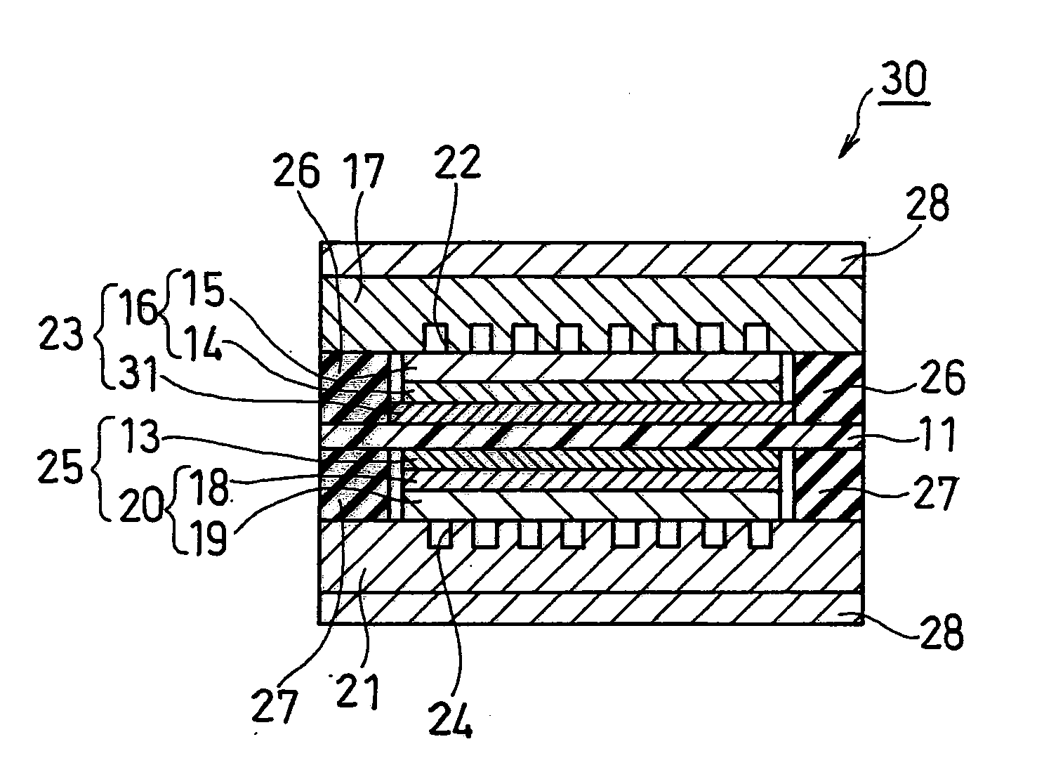
[0104]As Example 1, the fuel cell according to the first embodiment as described above was fabricated (see FIG. 1).

[0105]For the anode catalyst powder forming the anode catalyst layer 31, a powder comprising conductive carbon particles having an average primary particle size of 30 nm with a platinum-ruthenium alloy (atomic ratio Rt:Ru=1:1) adhering thereto, and containing the platinum-ruthenium alloy in a ratio of 50% by weight was used. For the cathode catalyst powder forming the cathode catalyst layer 13, a powder comprising conductive carbon particles having an average primary particle size of 30 nm with platinum adhering thereto, and containing the platinum in a ratio of 50% by weight was used. For the polymer electrolyte membrane 11, a 178-μm-thick fluorine-based polymer membrane (a film made of a base of a perfluorosulfonic acid / polytetrafluoroethylene copolymer (H+ type), product name: “Nafion (registered trademark) 117”, available from E.I. du Pont de Nemours and Company) wa...

example 2

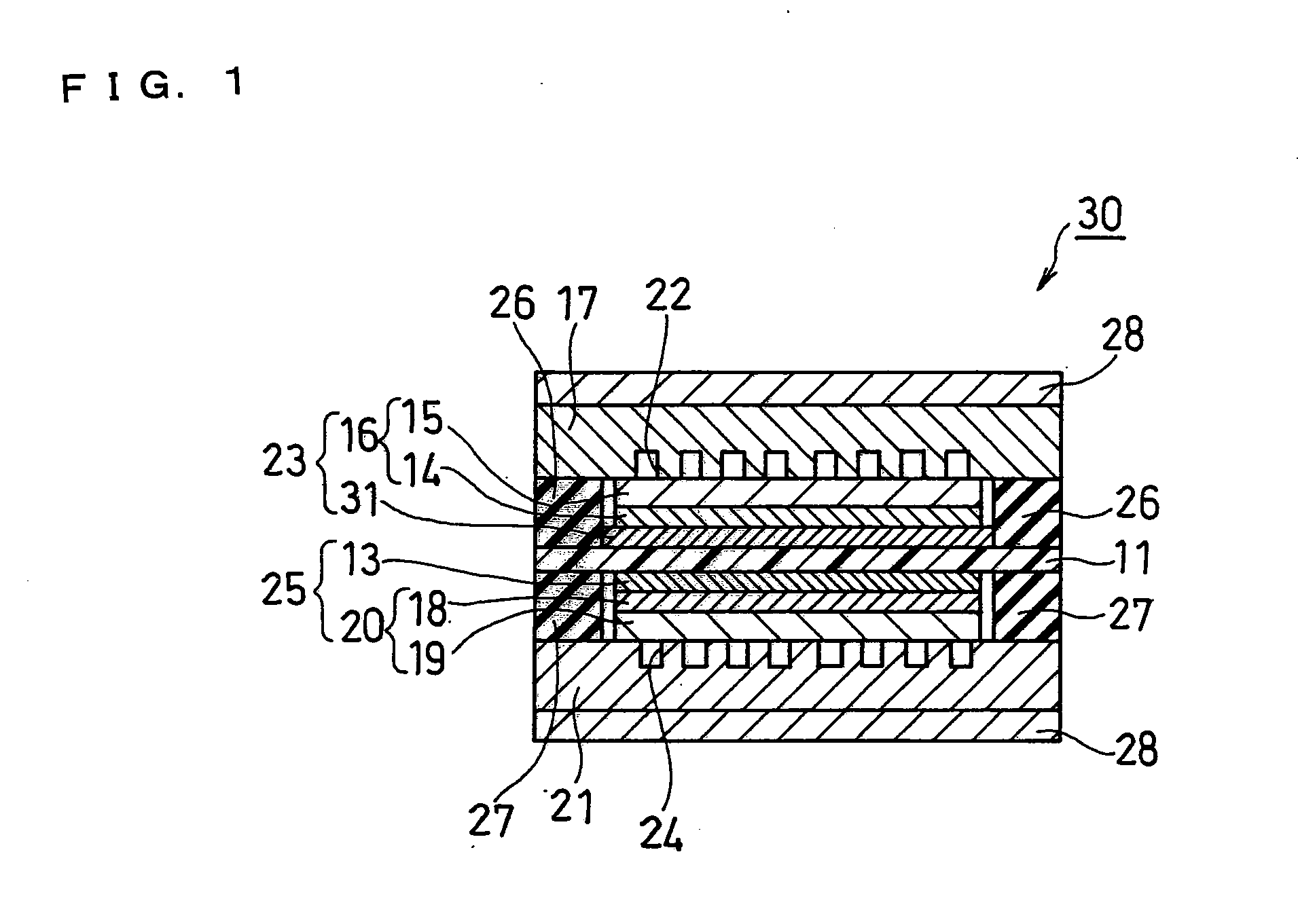
[0117]As Example 2, the fuel cell according to the second embodiment as described above was fabricated (see FIG. 2).

[0118]The anode diffusion layer 16 was produced in the same manner as in Example 1 and cut into a 60 mm square. Subsequently, an ink for forming an anode catalyst layer prepared in the same manner as in Example 1 was applied onto the surface of the anode diffusion layer 16 in the anode water-repellent layer 14 side by a spray method. In this process, the ink was applied onto the anode diffusion layer 16 with the end surface being left unprotected by masking or the like. By doing this, the ink for forming an anode catalyst layer was also adhered onto the end surface of the anode diffusion layer 16. In other words, the anode catalyst layer 33 was formed not only on the surface of the anode diffusion layer 16 in the anode water-repellent layer 14 side but also on the end surface thereof. Further, the entire end surface of the anode diffusion layer 16 was covered with the ...

example 3

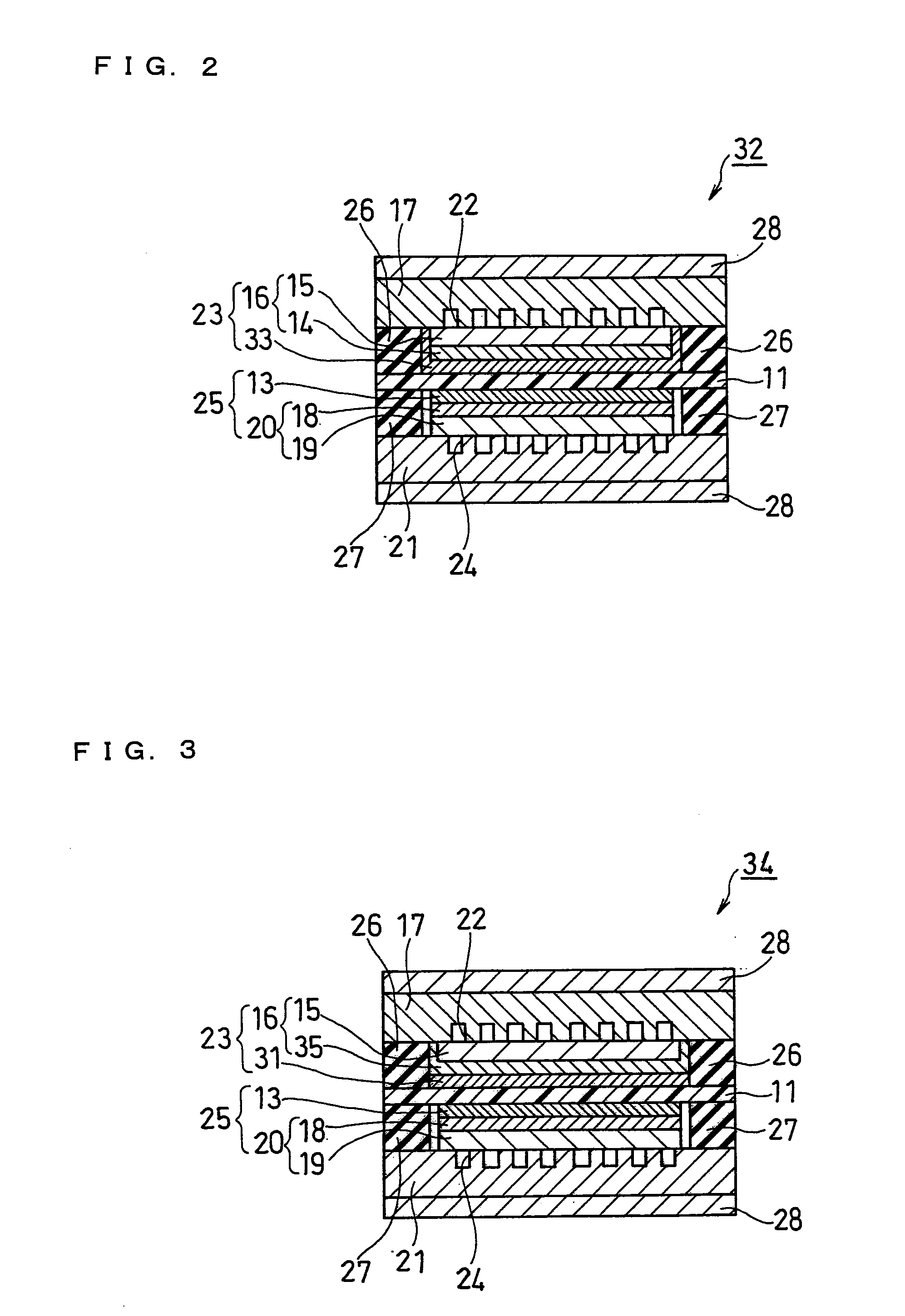
[0120]As Example 3, the fuel cell according to the third embodiment as described above was fabricated (see FIG. 3).

[0121]The anode porous substrate 15 was produced in the same manner as in Example 1 and cut into a 60 mm square. Subsequently, an ink for forming an anode water-repellent layer was applied onto the surface of the anode porous substrate 15 by a spray method. In this process, the ink was applied onto the anode porous substrate 15 with the end surface being left unprotected by masking or the like. By doing this, the ink for forming an anode water-repellent layer was also adhered onto the end surface of the anode porous substrate 15. In other words, the anode water-repellent layer 35 was formed not only on the surface of the anode porous substrate 15 in the anode catalyst layer 33 side but also on the end surface thereof. Further, the entire end surface of the anode porous substrate 15 was covered with the anode water-repellent layer 35.

[0122]A unit cell of a fuel cell (DMF...


PUM

PropertyMeasurementUnit
hydrogen ion conductivityaaaaaaaaaa
thicknessaaaaaaaaaa
areaaaaaaaaaaa

Abstract

The present invention intends to provide a fuel cell being capable of preventing the methanol crossover in a simple and easy manner and being excellent in fuel utilization rate and the like. A fuel cell 30 of the present invention includes a polymer electrolyte membrane 11, an anode 23 and a cathode 25 sandwiching the polymer electrolyte membrane 11, an anode-side separator 17 having a fuel flow channel, a cathode-side separator 21 having an oxidant flow channel, and gaskets 26 and 27 interposed between the anode-side and cathode-side separators 17 and 21 and the periphery of the polymer electrolyte membrane 11. In the fuel cell 30, the orthographic projection area of the anode catalyst layer 31 included in the anode 23 seen from the direction normal to an MEA is set to be larger than the orthographic projection area of the anode porous substrate 15 included in the anode 23 seen from the direction normal to the MEA.

Description

FIELD OF THE INVENTION[0001]The present invention relates to direct oxidation fuel cells, and specifically relates to an improvement of the cell structure in direct methanol fuel cells and the like.BACKGROUND OF THE INVENTION[0002]Fuel cells can be classified into polymer electrolyte fuel cells, phosphoric acid fuel cells, alkaline fuel cells, molten carbonate fuel cells, solid oxide fuel cells, and the like, according to the type of electrolyte used therein. Among them, polymer electrolyte fuel cells (PEFCs), because of their low operational temperatures and high output densities, have been put into practical use as a power source for automobiles and for use in the home cogeneration systems.[0003]Further, in recent years, the application of fuel cells as a power source for portable small-sized electronic devices such as laptop personal computers, cell phones, and personal digital assistants (PDAs) has been examined. Fuel cells can generate power continuously as long as fuel is supp...

Claims


Application Information

Patent Timeline
Patent Type & Authority Applications(United States)
IPC IPC(8): H01M8/10
CPCH01M8/02H01M8/0276H01M8/04186Y02E60/523H01M8/1011H01M2008/1095H01M8/04223Y02E60/50H01M8/0258
Inventor AKIYAMA, TAKASHI
Owner PANASONIC CORP
Why Eureka
Try Eureka