Brine purification

a technology of brine and sodium chloride, which is applied in the direction of crystal growth process, alkali metal halide purification, separation with moving sorbents, etc., can solve the problems of undetectable corrosive or toxic chlorinated organic compounds, difficult to remove, and the level of sodium chloride (nacl) is too high for direct discharge, so as to reduce the content of high total organic carbon (toc)

Inactive Publication Date: 2010-09-02
DOW GLOBAL TECH LLC
View PDF10 Cites 61 Cited by
  • Summary
  • Abstract
  • Description
  • Claims
  • Application Information

AI Technical Summary

Benefits of technology

[0026]The present invention provides methods for reducing high total organic carbon (TOC) contents of brine streams having a high concentration of sodium chloride, such as a brine by-product stream from the production of epichlorohydrin from glycerin, without deleterious precipitation of the sodium chloride in separation equipment, which can be practiced under a

Problems solved by technology

The presence of sodium chloride may pose difficulties in the removal of organic compounds from various brine by-product streams because some removal processes may cause deleterious precipitation of the sodium chloride in separation equipment.
Also, the presence of the chloride ion may result in the formation of undesirably corrosive or toxic chlorinated organic compounds during chemical treatment to destroy the organic compounds.
The brine stream may also contain a variety of organic compounds, some of which may be difficult to remove by traditional techniques such as extraction or carbon bed treatment.
The level of sodium chloride (NaCl) is too high for direct discharge, after TOC removal, to the environment.
The concentration of NaCl is also too high for effective biological wastewater treatment without significant consumption of fresh water and a corresponding increase in the necessary capacity of the wastewater operation.
However, the major component of the TOC is glycerin which is difficult to remove by traditional techniques such as extraction or carbon bed treatment.
However the processes employ harsh reaction conditions of high temperatures, which are above 130 degrees centigrade (° C.
However, such electrical treatment is not directed to the treatment of contaminated brine to reduce contaminants therein, or for use of the purified brine as process streams, including feed and recycle process streams.
A problem associated with using aqueou

Method used


Image

  • Brine purification
  • Brine purification
  • Brine purification

Examples


example 1

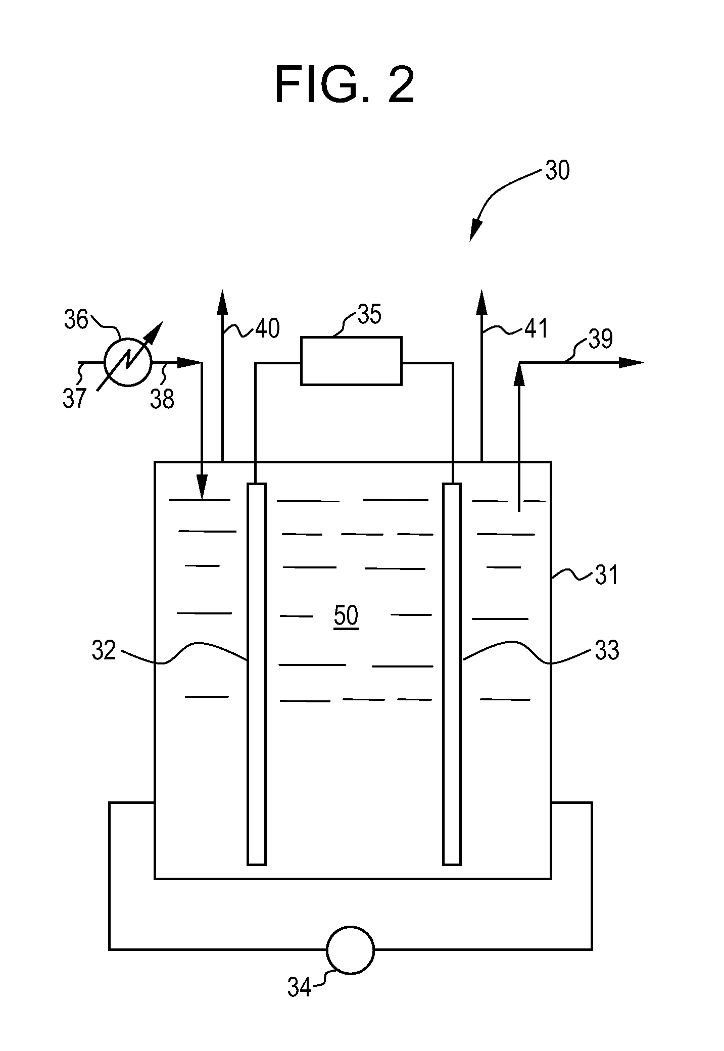
[0464]The equipment used in this Example 1 consisted of a jacketed glass reactor of 0.32 liter effective volume, equipped with a holder to which an anode and cathode were attached; a magnetic agitator; a short pipe inlet piece connected to a peristaltic pump for feed supply from a storage vessel; a short pipe outlet piece for overflow of the reactor effluent into a collecting vessel; and a thermostat connected to the inlet and outlet pipe pieces of the reactor jacket. The electrodes were connected to the appropriate poles of a rectifier operated with 220 V power supply. The reactor jacket was further connected to a cryostat which was adjusted to maintain the temperature of the reactor contents at constant 40° C.

[0465]The reactor was filled with raw brine with a sodium chloride content of 18% and an organic content corresponding to 1700 mg / l dissolved organic carbon (DOC), adjusted to a pH of 10. The feed storage vessel contained the same material. After starting the agitator and the...

example 2

[0466]0.32 l of brine containing 19.8% sodium chloride and 1900 mg / l DOC content was placed in the reactor and about 1000 ml of the same material in the feed storage vessel. The reaction was carried out under otherwise same conditions as described in Example 1 above but at a current adjusted to constant 10 A. The energy uptake was 0.145 kWh, the feed rate was 1.3 ml / min corresponding to a mean hydraulic residence time of 4 hours in the reactor. The effluent was collected as before and analyzed. The DOC content was 35 mg / l, the chlorate content was 5850 mg / l and the sodium hypochlorite content was 7550 mg / l. 100 ml of this material were placed in a round-bottom flask as in the previous experiment and acidified to pH 1.5 by addition of 32% hydrochloric acid. The contents were heated to 100° C. and agitated at this temperature for 60 minutes. A sample was then withdrawn and analyzed for sodium hypochlorite by iodine titration with potentiometric endpoint recognition. The sodium hypochl...

example 3

[0467]In this Example 3, microbes are selected and adapted according to the present invention.

[0468]3.5 g / liter of a diverse microbial population comprising the species Vibrio alginolyticus, Halomonas salina, and / or Halomonas campaniensis is introduced into a bioreactor vessel containing an aqueous brine solution containing 3.5 wt % sodium chloride and 500 mg / liter glycerol. The aqueous brine solution is fed at a rate in the range from 0.1 to 1.5 kg glycerol per kg microbes per day so as to maintain a 50 mg / liter glycerol concentration at the bioreactor outlet. A comparable outflow of the mixture in the bioreactor is provided to maintain a constant unit volume within the bioreactor. Sufficient nutrients are added to the aqueous brine stream to maintain the NH4—N concentration at the bioreactor outlet at 10 mg / liter and the orthophosphate concentration at the bioreactor outlet at 5 mg / liter. The sodium chloride concentration is raised at a rate of about 0.5 wt % per 4 hydraulic resid...


PUM

PropertyMeasurementUnit
Temperatureaaaaaaaaaa
Fractionaaaaaaaaaa
Fractionaaaaaaaaaa

Abstract

Process and apparatus for reducing organic content of brine comprising subjecting a brine solution to at least two purification treatments selected from electrochemical treatment, chlorinolysis, or other chemical oxidation treatment, carbon adsorption, extraction, biological treatment and chrystallizing treatment; wherein the organic content of purified brine is sufficiently low to enable sense of the purified brine in an industrial process.

Description

CROSS-REFERENCE TO RELATED APPLICATIONS[0001]The present application is related to the following applications, filed on even date herewith, with the disclosures of each the applications being incorporated by reference herein in their entireties:[0002]Application Ser. No. ______ (Attorney Docket No. 66324), filed on even date herewith, entitled “Total Organic Carbon TOC) Reduction in Brine Via Chlorinolysis”.[0003]Application Ser. No. ______ (Attorney Docket No. 66325), filed on even date herewith, entitled “Process and Apparatus for Purification of Industrial Brine”.[0004]Application Ser. No. ______ (Attorney Docket No. 66326, filed on even date herewith, entitled “Process, Adapted Microbes, Composition and Apparatus for Purification of Industrial Brine”.[0005]Application Ser. No. ______ (Attorney Docket No. 66327), filed on even date herewith, entitled “Brine Purification”.BACKGROUND OF THE INVENTION[0006]1. Field of the Invention[0007]The present invention relates to purified brin...

Claims


Application Information

Patent Timeline
IPC IPC(8): B01D9/00C02F3/00C02F1/76C02F1/46B01D15/04C02F1/461C25B1/16C25B9/00C09K3/00
CPCB01D9/0031C01D3/14C02F2209/20C01D3/16C02F1/265C02F1/283C02F1/4674C02F1/72C02F3/02C02F3/34C02F9/00C02F2101/30C02F2209/02C02F2209/06B01D9/004C25B1/46C25B15/08Y02W10/10
Inventor HOOK, BRUCETIRTOWIDJOJO, DANKOESTER, FRANKCHAUDHARY, SUNIL K.MEHTA, ANILCHAUVEL, JR., JEANCHRISTENSON, CHRISFRANK, TIMOTHYPEREIRA, CELIO LUMEGLUCK, STEVELORD, GLENNWEST, DAVIDLUNDSTROEM, CHRISTINEHORN, ANNETTLENGYEL, ISTVAN
Owner DOW GLOBAL TECH LLC
Why Eureka
Try Eureka