Method and system for producing synthetic gas from biomass by high temperature gasification

a high temperature gasification and biomass technology, applied in the field of synthetic gas production, can solve the problems of poor heat exchange effect, large amount of tar, low heating value of synthetic gas, etc., and achieve the effect of reducing the temperature of the burner nozzle, reducing the heating rate and improving the working efficiency of the system

Inactive Publication Date: 2010-09-09
WUHAN KAIDI ENG TECH RES INST CO LTD
View PDF13 Cites 19 Cited by
  • Summary
  • Abstract
  • Description
  • Claims
  • Application Information

AI Technical Summary

Benefits of technology

[0028]In the invention, external combustible gas and external oxygen are used, and by adjusting the proportion thereof, the temperature of the carbonization furnace, the temperature of the burner nozzle of the carbonization furnace, and the heating rate can be controlled effectively. The invention has achieved the following objectives: a) to provide heat for the carbonization of biomass by a direct combustion between the external combustible gas and oxygen; b) if the external combustible gas is excess, the excess part can be used as inert gas to absorb heat so as to reduce the temperature of the burner nozzle of the carbonization furnace; however, if real inert gas having no hydrocarbon is introduced to reduce the temperature of the burner nozzle of the carbonization furnace, a large amount of inert gas will enter the gasification system, which means the working efficiency of the system and the quality of the synthetic gas will decrease significantly; c) since the combustible gas is excess, only part of combustible gas is consumed, the excess gas will be consumed in the gasifier, which improves the efficiency of energy utilization.
[0029]Therefore, the introduction of external combustible gas can improve the gasification efficiency, reduce the oxygen consumption of the synthetic gas, and enhance the energy conversion rate of the system. Compared with the method for producing synthetic gas by combined cycle gasification mentioned ab

Problems solved by technology

However, the temperature in the fixed bed is nonuniform, the heat exchange effect is poor, the synthetic gas has a low heating value, and a large amount of tar is produced.
However, it is sensitive to the characteristics of raw materials.
If the adhesion, thermal stability, moisture content, or ash melting point of raw materials changes, the operation will become abnormal.
Furthermore, the synthetic gas has a large amount of tar.
Since a large amount of tar is produced in the fixed bed and the fluidized bed, a tar cracking unit and purification equipment must be installed, which results in a complicated process.
Based on current grinding technology, there is no way to grind biomass having much cellulose to a size suitable for the entrained flow bed.
So the entrained flow bed cannot be used for gasification of biomass.
Nowadays, tar cracking and pretreatment of biomass prior to gasification are tough problems for the development of biomass gasification.
In the method, pyrolysis gas and charcoal experience incomplete combustion in the gasifier at around 1000° C., and tar is cracked under high temperature.
Secondly, due to a low temperature in the combustion reaction, the average temperature in the reduction zone is less than 700° C., and thereby the yield of effective synthetic gas (CO and H2) is decreased significantly (about 30%).
Thirdly, the ash and unreacted carbon residue from the reduction reaction is directly discharged, resulting in a low carbon conversion rate.
Finally, the gasifier used in the method is in the form of a fixed bed, since the reduction reaction absorbs heat, the temperature difference between the top and the bottom (the top is about 1000° C. and the bottom is about 500° C.) of the bed is huge, which is an inherent disadvantage of fixed bed.
However, during carbonization stage, solid products are not ground prior to transporting to the reaction coils of the gasifier, which will affect the speed and degree of gasification reaction.
Secondly, since the gasification reaction happens in the reaction coil, a large amount of transport ga

Method used


Image

  • Method and system for producing synthetic gas from biomass by high temperature gasification
  • Method and system for producing synthetic gas from biomass by high temperature gasification

Examples


example 1

[0043]Take wood as a raw material of biomass. The elemental composition and characteristic data of the dried wood are listed in Table 1.

TABLE 1Elemental composition and characteristic data of the dried woodItemsSymbolUnitValueCarbonCar%(Kg / Kg)39.43HydrogenHar%(Kg / Kg)5.21OxygenOar%(Kg / Kg)38.36NitrogenNar%(Kg / Kg)0.15SulfurSar%(Kg / Kg)0.21ChlorineClar%(Kg / Kg)0.00AshAar%(Kg / Kg)5.00MoistureMar%(Kg / Kg)11.64Ash fusion pointFT° C.1436Low heat valueLHVMJ / Kg14.75

[0044]Take natural gas as external combustible gas. The elemental composition and characteristic data of the external combustible gas are listed in Table 2.

TABLE 2Components and characteristic data of natural gasComponentsValueCH491.746%C2H64.480%C3H82.257%CO20.070%O20.040%N21.406%H2S concentration (mg / Nm3)20.00Low heat value (kcal / m3)9000.8

[0045]The main operating conditions are set as follows:

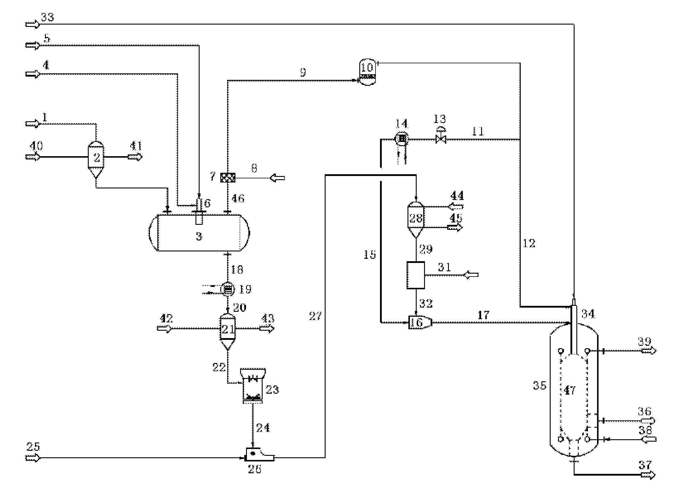
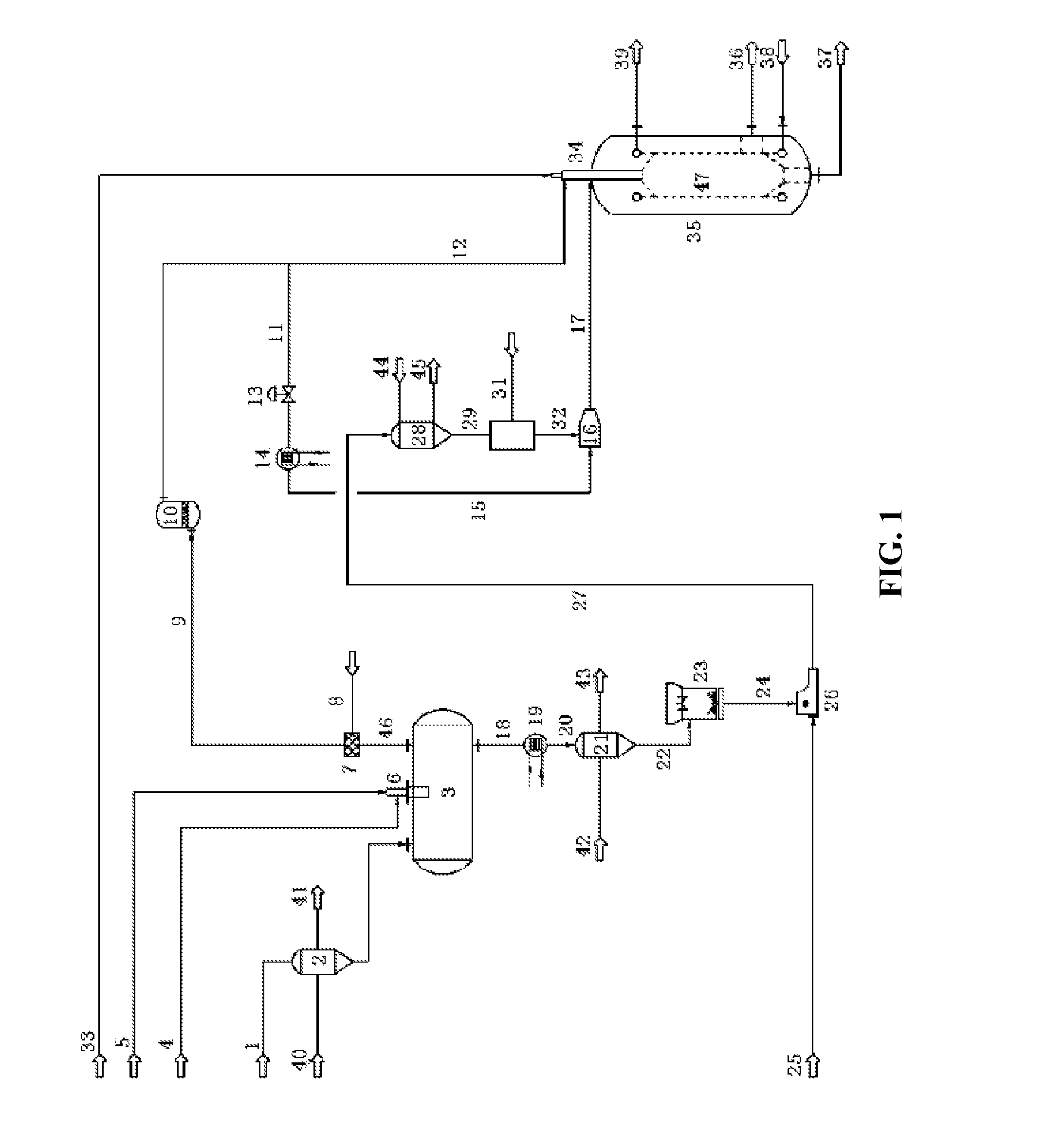
[0046]1) The transportation amount of biomass into the carbonization furnace 3 via the supercharging feeding system of biomass 2 is 4.07 kg / s.

[...

example 2

[0067]Take wood as a raw material of biomass (as shown in Table 1). Take natural gas as external combustible gas (as shown in Table 2). The temperature of the carbonization furnace 3 is 600° C. The heating rate of pyrolysis of the biomass in the carbonization furnace 3 is 100° C. / s. Other operating conditions are the same as that in Example 1.

[0068]Based on the above conditions, the main flow rate and performance parameters of the system are as follows:

[0069]1) The mass flow rate of the external combustible gas (40° C.) entering the carbonization furnace 3 is 0.33 Kg / s.

[0070]2) The mass flow rate of the external oxygen (160° C.) entering the carbonization furnace 3 is 0.63 Kg / s.

[0071]3) The flame temperature of the burner nozzle 6 of the carbonization furnace 3 is 1700° C.

[0072]4) The total weight of the pyrolysis gas produced in the carbonization furnace 3 is 3.84 Kg / s.

[0073]5) The total weight of the charcoal produced in the carbonization furnace 3 is 1.19 Kg / s.

[0074]6) The combus...

example 3

[0081]Take wood as a raw material of biomass (as shown in Table 1). Take natural gas as the external combustible gas (as shown in Table 2). The input amount of the external combustible gas (mole) is 5 times that required for a complete combustion with the input oxygen. Other operating conditions are the same as that in Example 1.

[0082]Based on the above conditions, the main flow rate and performance parameters of the system are as follows:

[0083]1) The mass flow rate of the external combustible gas (40° C.) entering the carbonization furnace 3 is 0.78 Kg / s.

[0084]2) The mass flow rate of the external oxygen (160° C.) entering the carbonization furnace 3 is 0.604 Kg / s.

[0085]3) The flame temperature of the burner nozzle 6 of the carbonization furnace 3 is 1200° C.

[0086]4) The total weight of the pyrolysis gas produced in the carbonization furnace 3 is 4.3 Kg / s.

[0087]5) The total weight of the charcoal produced in the carbonization furnace 3 is 1.19 Kg / s.

[0088]6) The combustible gas whic...


PUM


Abstract

A method for producing synthetic gas from biomass by high temperature gasification, by: feeding biomass, carbonizing to yield pyrolysis gas and charcoal, pulverizing the charcoal, and gasifying in a gasifier. The heat source for the carbonizing step comes from a direct combustion reaction between external combustible gas and external oxygen in a carbonization furnace. Also provided is a device for producing synthetic gas from biomass by high temperature gasification, containing at least: a supercharging feeding system for biomass, a carbonization furnace containing at least a burner nozzle, a pulverizing system, a transportation system for charcoal powder, a gasifier, a pneumatic conveying system, and a plurality of connecting pipes therefor; the burner nozzle of the carbonization furnace is connected to an external combustible gas pipe and an external oxygen pipe respectively.

Description

CROSS-REFERENCE TO RELATED APPLICATIONS[0001]This application is a continuation of International Patent Application No. PCT / CN2008 / 073672 with an international filing date of Dec. 24, 2008, designating the United States, now pending, and further claims priority benefits to Chinese Patent Application No. 200810236614.4 filed Nov. 28, 2008. The contents of all of the aforementioned applications, including any intervening amendments thereto, are incorporated herein by reference.BACKGROUND OF THE INVENTION[0002]1. Field of the Invention[0003]The invention relates to the production of synthetic gas, and more particularly to a method and a system for producing synthetic gas from biomass by high temperature gasification.[0004]2. Description of the Related Art[0005]Biomass, an organic matter generated by plants through photosynthesis, has wide sources and large available quantity. It can be transformed into clean gas or liquid fuel for power generation and producing industrial raw materials...

Claims


Application Information

Patent Timeline
IPC IPC(8): B01J7/00C10J3/46
CPCC10J3/466C10J3/66C10J2200/152C10J2300/0906C10J2300/0916Y02E50/14C10J2300/094C10J2300/0959C10J2300/1207C10J2300/1223C10J2300/1693C10J2300/092Y02P20/145Y02E20/18Y02E50/10C10B53/02C10J3/00C10L3/00
Inventor YANG, ZHANCHUNZHANG, HAIQINGCAO, MINXIACHEN, ANHELI, HONG
Owner WUHAN KAIDI ENG TECH RES INST CO LTD
Why Eureka
Try Eureka