Microfluidic device

a microfluidic device and microfluidic technology, applied in fluid controllers, laboratory glassware, thin material processing, etc., can solve the problems of low specificity, low sensitivity and specificity of microarray technology, and tedious manual loading of pcr sample into individual reaction wells of pcr chips, so as to prevent cross-contamination and sample evaporation

Inactive Publication Date: 2010-10-07
GONG HAI QING +2
View PDF3 Cites 31 Cited by
  • Summary
  • Abstract
  • Description
  • Claims
  • Application Information

AI Technical Summary

Benefits of technology

[0010]The present invention provides a microfluidic device comprising a plurality of wells, each of which may be substantially filled with a liquid without either the need for expensive individual sample loading or the requirement to isolate and seal individual wells to prevent cross-contamination and sample evaporation.

Problems solved by technology

Moreover, the sensitivity and specificity of microarray technology is low and the multiple steps involved in this technology introduce variability in the results when compared to real-time PCR.
However, studies show that solid-phase PCR is less efficient than solution-phase PCR.
Problems associated with the devices developed to date include: the tedious manual loading of the PCR sample into the individual reaction wells of the PCR chip; the substantial expense of liquid-dispensing robots for loading the wells with solutions; or problems associated with the immobilization of the nucleotide primers within a gel matrix.
It is complicated, however, to isolate and seal all the chambers using mechanical valves because the inlet and outlet channels of each of the microchambers have to be sealed to prevent PCR mixture evaporation during thermocycling and to prevent primer pair cross-contamination.
In addition, the channels in such configuration occupy space on the chip and limit the density of chambers on the chip.
Sample loading and other liquid handling operations, however, are achieved using high precision robots, which are expensive and require skilled operators.
Few researchers have used microfluidic liquid distribution for performing PCR on a chip.

Method used


Image

  • Microfluidic device
  • Microfluidic device
  • Microfluidic device

Examples


example 1

Construction of a Device for PCR

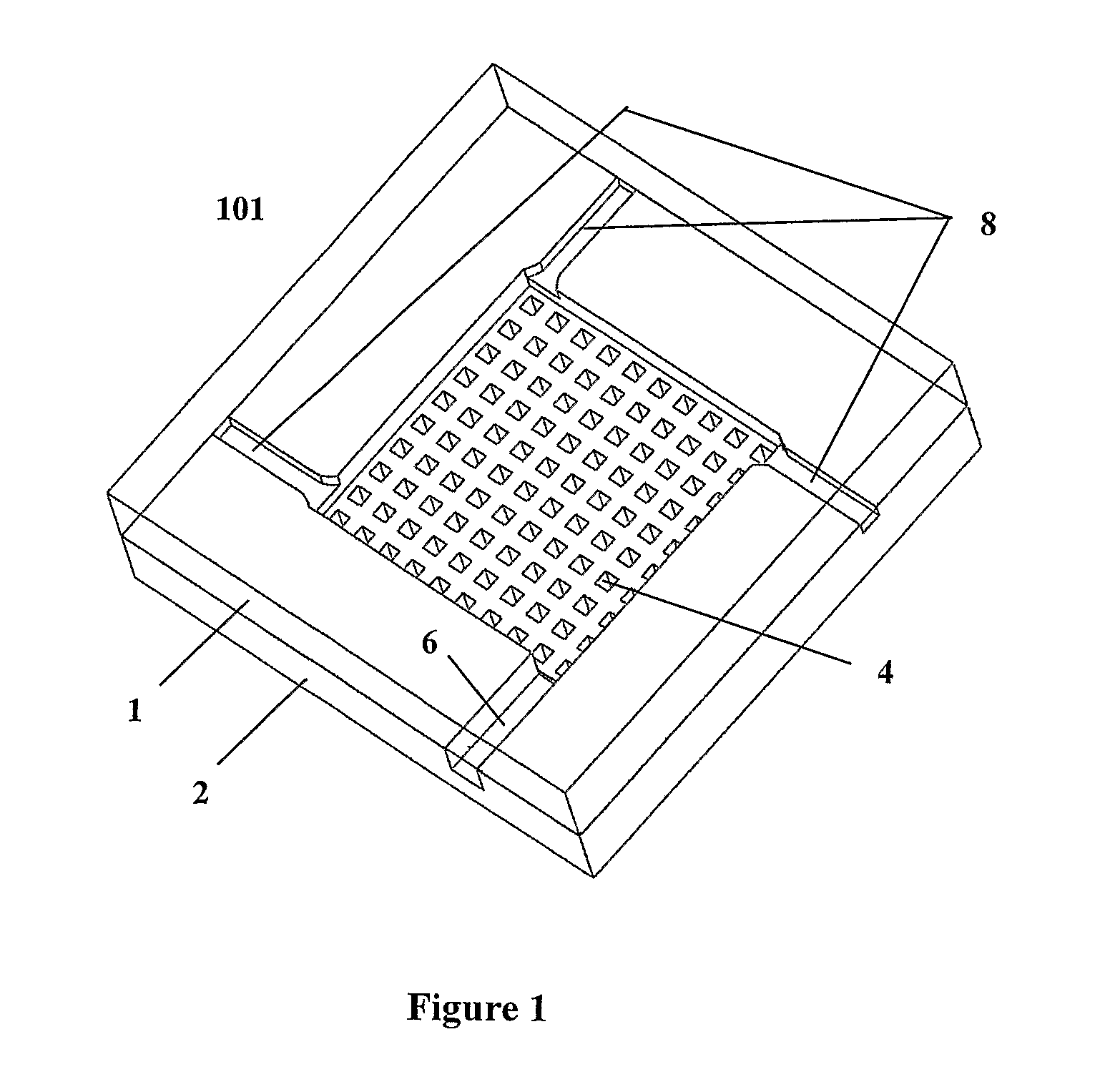
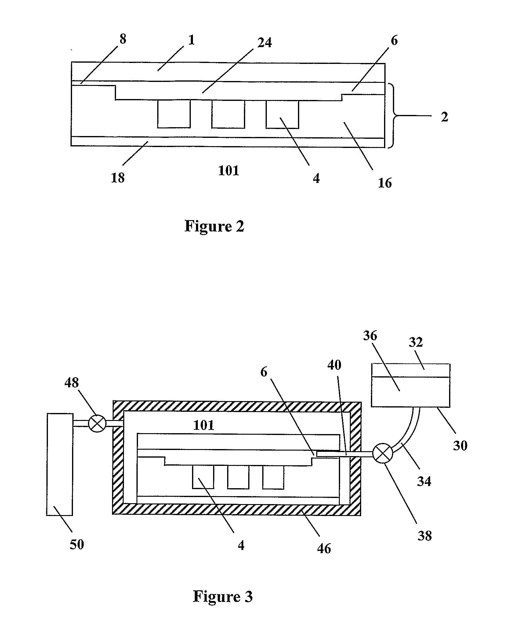
[0056]An example of a device with the largest face measuring 5×5 cm, and possessing 100 wells each of dimensions 0.5×0.5×0.5 mm, was prepared as follows. Liquid prepolymer (2 mL) was prepared by mixing 10 parts PDMS Sylgard Silicone Elastomer 184 and 1 part Sylgard Curing Agent 184 (Dow Corning Corporation Midland, Mich., USA) to homogeneity with a magnetic stirrer at 150 rpm for 1 hour in a beaker. The PDMS prepolymer was applied to the surface of a metal die (micro EDM machined stainless steel) with reversed shape of the wells and channels, and the liquid prepolymer degassed under vacuum for 20 minutes. Subsequently, another metal block with a flat surface was placed on top of the PDMS prepolymer and the entire assembly was heated to 80° C. for 2 hours. The PDMS replica layer with nanowells and microchannels was carefully removed from the mould and the flat surface of the polymer subsequently bonded to a 0.1 mm thick acid-washed borosilicate glass s...

example 2

Cross-Contamination

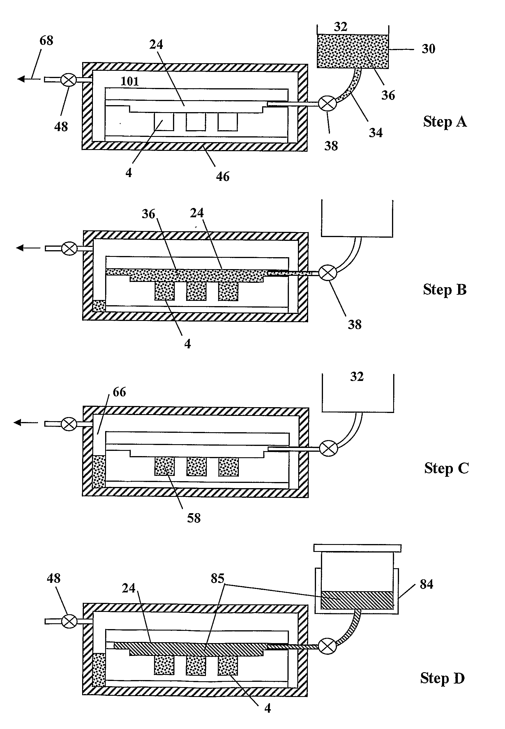
[0058]It has been demonstrated that during the process of substantially filling the wells, there is negligible cross-contamination of chemical substances preloaded into the wells. In this respect a predetermined number of wells within a device comprising 100 equal volume wells were preloaded with a solution containing a blue dye. The solvent was subsequently evaporated from the wells of the device. Driven by a vacuum according to a method of the present invention, the wells and headspace were filled with a liquid which was a suitable solvent for the blue dye, before the headspace was appropriately evacuated. It was observed that essentially all of the blue dye remained in each of the wells into which it had been preloaded.

[0059]To further validate the finding of negligible cross-contamination, a select number of wells of another device were preloaded with a solution of purified 20 mer long oligonucleotides (primers) tagged with FAM fluorophore (5′-(6 FAM)-TCG TGC ...

example 3

Real-Time PCR Method

[0060]The devices, systems and methods of the present invention have been applied to the field of real-time PCR. Twenty-two wells of a device of the present invention comprising a total of 100 wells were preloaded with solutions containing primers pairs, leaving the remaining 78 wells empty. The solvent was subsequently evaporated leaving dried primer pairs. The sequences of forward and reverse primers were 5′-ATG AAT TAC CAA GTC AAT GGT TAC-3′ (24 mer) and 5′-CAT AAC CAG TCG GTA CAG CTA-3′ (21 mer). The wells of the device were filled with PCR mixture containing a fixed concentration of DNA template using a method of the present invention. The PCR mixture contained 10 mM Tris-HCl (pH 8.4), 50 mM KC1, 0.1% Triton X-100, 0.2 mM each of dATP, dCTP, dTTP and dGTP, 3 mM MgCl2 0.2 U / μL of Taq DNA polymerase (Promega, Madison, USA), 1.5 μg / μL BSA, 2×SYBR Green I (Cambrex Biosciences, Maine, USA) and 0.01 ng / μL of the BNI-1 fragment (189 bp) of SARS DNA cloned in pGEM-3...


PUM


Abstract

The present invention provides a microfluidic device comprising a plurality of wells, each of which may be substantially filled with a liquid without either the need for expensive individual sample loading or the requirement to isolate individual wells to prevent cross contamination and sample evaporation. A base member (2) comprises a plurality of wells (4) in the form of an array, an inlet channel (6) and three outlets (8).

Description

TECHNICAL FIELD[0001]The invention relates to microfluidic devices, and systems and methods for use of such devices. The invention is particularly suitable for use in Polymerase Chain Reaction (PCR) applications and it will be convenient to describe the invention with reference to that application. However it is to be understood that the devices, systems, and methods of the invention are suitable in other applications.BACKGROUND ART[0002]The completion of the Human Genome Project triggered a rapid development of high-throughput platforms for parallel genomic assays. Currently, two types of DNA microarrays are widely used as platforms for highly parallel genomic assays: microarrays for genome-wide expression profiling and microarrays for single nucleotide polymorphism (SNP) detection and genotyping. The validation of microarray results remains a desirable step due to non-standard methods of data analysis and interpretation. Quantitative reverse transcription PCR (qRT-PCR) is often us...

Claims


Application Information

Patent Timeline
Patent Type & Authority Applications(United States)
IPC IPC(8): F16L41/00
CPCB01L3/5025B01L3/50853B01L2400/049B01L2300/0829B01L2200/0642Y10T137/85938
Inventor GONG, HAI-QINGHUI, KAM MANLIU, HAO-BING
Owner GONG HAI QING
Why Eureka
Try Eureka