

Vacuum processing apparatus and operating method for vacuum processing apparatus
a vacuum processing and vacuum processing technology, applied in the direction of hollow article cleaning, nuclear engineering, transportation and packaging, etc., can solve the problems of reducing the processing capacity affecting the production efficiency of vacuum processing apparatus, and deteriorating the quality of film deposition, so as to improve the production efficiency of the vacuum processing apparatus, the influence of the operating time of the self-cleaning procedure on the film deposition-related operating time is small, and the effect of convenient setting
- Summary
- Abstract
- Description
- Claims
- Application Information
AI Technical Summary
Benefits of technology
Problems solved by technology
Method used
Image

Examples
first embodiment
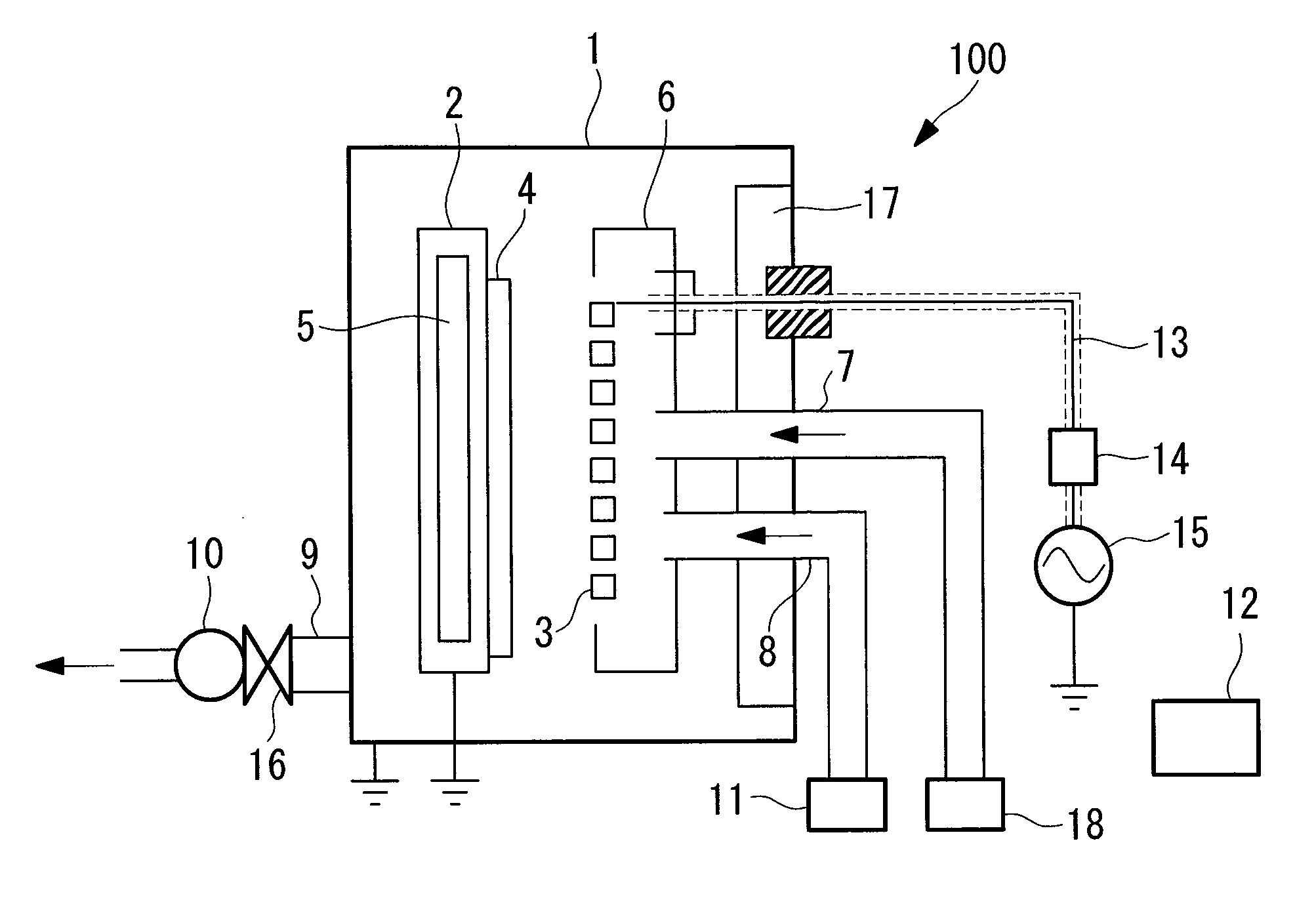
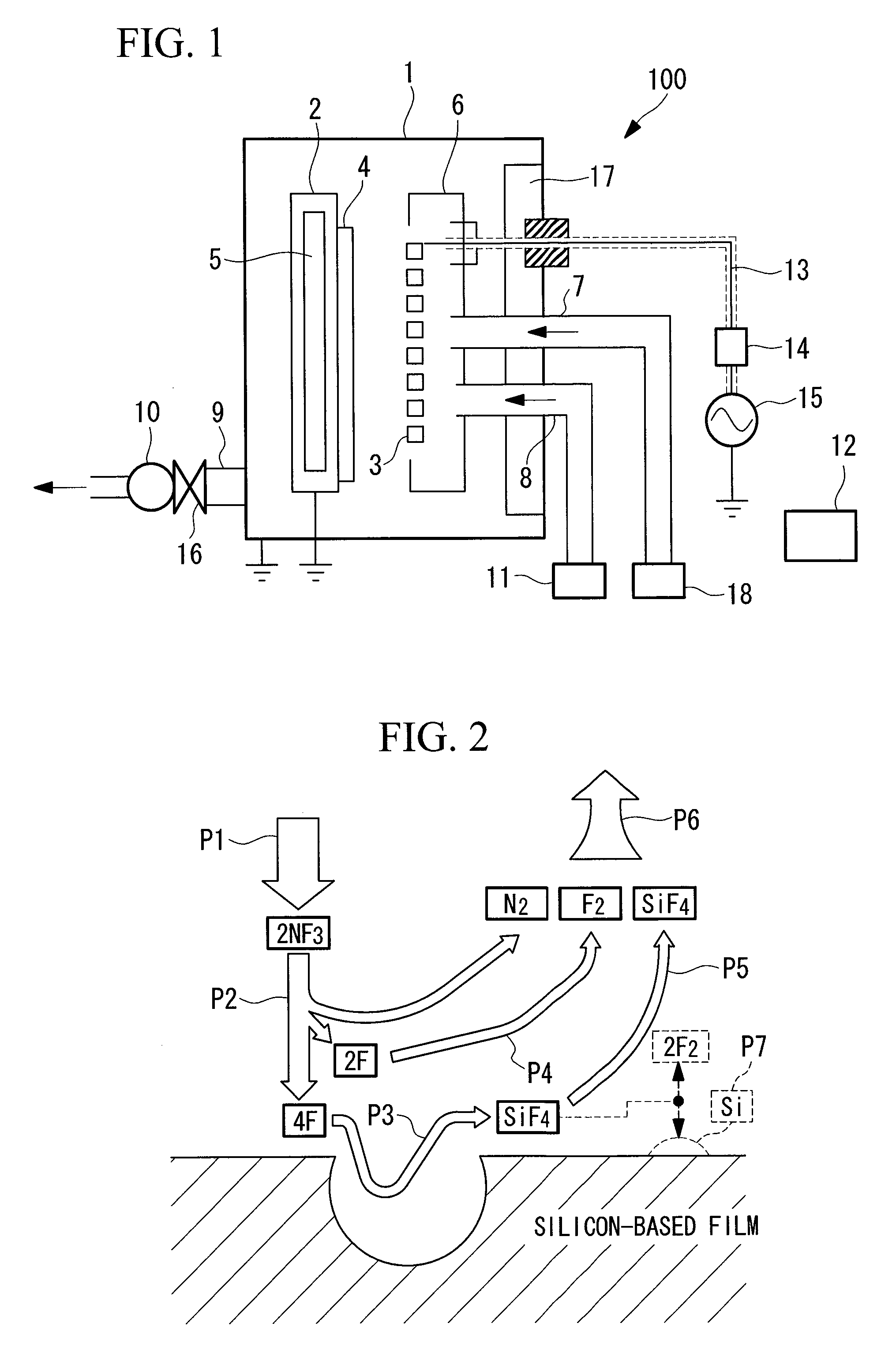
[0121]A plasma CVD apparatus (vacuum processing apparatus) 100 according to a first embodiment of the present invention will be explained with reference to FIG. 1 to FIG. 4.
[0122]FIG. 1 is a cross-sectional view that shows the general structure of a plasma CVD apparatus 100.
[0123]The plasma CVD apparatus 100 is provided with a film deposition chamber 1, a heater cover 2, a heater 5, a discharge electrode 3, an electrode cover 6, a source gas feed pipe 7, a cleaning gas feed pipe 8, a gas exhaust pipe 9, a vacuum pump 10, a cleaning gas supply portion 11, a controller 12, a radio frequency energy supplying coaxial cable 13, an impedance matching device 14, a radio frequency power source 15, a pressure regulating valve 16, a hest energy reservoir (hest energy reservoir member) 17, and a source gas supply portion 18.
[0124]The film deposition chamber 1 is a vacuum container, and forms a silicon-based thin film layer (an amorphous silicon film or a microcrystalline silicon film) and the ...
second embodiment
[0202]Next, the plasma CVD apparatus 100 according to a second embodiment of the present invention will be explained with reference to FIG. 5.
[0203]The present embodiment differs from the first embodiment only on the point that the heat capacity (mass×specific heat) of the discharge electrode 3 and the electrode cover 6 is made larger, and thus, here, redundant explanations will be omitted. The other structures are identical, and thus, here, the redundant explanations thereof will be omitted.
[0204]FIG. 5 shows the heat balance inside the film deposition chamber 1 during self-cleaning procedure. The main heat inputs to the film deposition chamber are the heat input 21 of the high frequency power, the generated heat 22 of the heater 5, and the exothermic reaction 23 of the etching. However, there is no need to take into account the heater 5 because it is inactive during the self-cleaning procedure etching time.
[0205]In contrast, the output heat from the film deposition chamber 1 consi...
third embodiment
[0217]Next, the plasma CVD apparatus 100 according to a third embodiment of the present invention will be explained with reference to FIG. 6 to FIG. 8.
[0218]The present embodiment differs from the first embodiment only on the point that the film deposition thickness of the pre-deposition film, which is the pre-deposition layer, is formed so as to be comparatively thick. The other structures are identical, and here, the redundant explanations thereof are omitted.
[0219]FIG. 7 shows a cross-sectional view in which a portion of the inside of the film deposition chamber has been removed. Among the constituents of the film deposition chamber 1, for example, a corrosion layer (FeF2, CrF2 and the like), due to a reaction between an iron component and a chrome component in the constituent material, is produced on the surface of constituents made of a stainless steel material, and this corrosion layer 31 grows to several 10 μms due to the repetition of the self-cleaning procedure.
[0220]After ...
PUM
| Property | Measurement | Unit |
|---|---|---|
| height | aaaaa | aaaaa |
| height | aaaaa | aaaaa |
| average roughness | aaaaa | aaaaa |
Abstract
Description
Claims
Application Information