
Method of forming metal complex compound, and organic electroluminescence device

a technology of metal complex compound and organic electroluminescence device, which is applied in the direction of discharge tube luminescnet screen, platinum organic compound, organic chemistry, etc., can solve the problems of low yield, deterioration of device durability, and inability to develop devices having high efficiency and high durability compatibility, so as to achieve excellent durability, reduce the content of decomposed material in light emitting materials, and enhance yield

Active Publication Date: 2011-03-03
UDC IRELAND
View PDF8 Cites 12 Cited by
  • Summary
  • Abstract
  • Description
  • Claims
  • Application Information

AI Technical Summary

Benefits of technology

[0075]Embodiments of the invention are methods of forming compounds represented by the formulae (1) to (8) which have nitrogen-containing heterocyclic 5-membered rings as partial structures of ligands thereof through the use of metal-metal exchange reaction. By carrying out the reaction at a low temperature in particular, decomposition reaction and side reaction of the 5-membered nitrogen-containing heterocyclic rings are retarded, and thus the decomposed-matter contents in light emitting materials are reduced and the yields can be enhanced. In addition, it becomes possible to provide organic EL devices of excellent durability.

Problems solved by technology

As the fluorescent materials, iridium complexes and platinum complexes have been known (see e.g. JP-A-2001-247859 and JP-A-2007-19462), but they haven't allowed development of devices having compatibility between high efficiency and high durability yet.
However, decomposition products resulting from high-temperature reaction and impurities of starting material origin were included in the products obtained by using those synthesis methods, and they constituted a factor causing deterioration in durability of devices.
Therefore their yields are low, and besides, there were cases in which products themselves were not obtained.
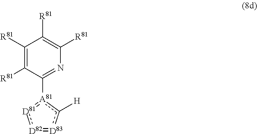
As to complexes having 5-membered nitrogen-containing heterocyclic rings as partial structures of ligands, however, high-acidity hydrogen atoms of the 5-membered nitrogen-containing heterocyclic rings cause exchange reaction with metals (Tetrahedron Letters, 1996, 27, 4095-4098), and therefore it has been difficult to synthesize complexes having intended coordination forms.

Method used


Image

  • Method of forming metal complex compound, and organic electroluminescence device
  • Method of forming metal complex compound, and organic electroluminescence device
  • Method of forming metal complex compound, and organic electroluminescence device

Examples


synthesis examples

(Synthesis of Exemplified Compound 1)

[0374]Exemplified Compound 1 was synthesized in accordance with the following reaction scheme (Synthesis Method 12).

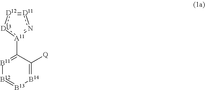
[0375]At a temperature of −78° C. under an atmosphere of nitrogen, a pentane solution of n-BuLi (2.6 ml, 4.2 mmol) was added dropwise to 10 ml of a dehydrated THF solution of the compound 1a (744 mg, 4 mmol), and stirred for 30 minutes. Thereto, a diethyl ether solution of anhydrous zinc(II) chloride (4 ml, 4 mmol) was further added dropwise, and stirring was continued until the temperature of the reaction solution was restored to room temperature.

[0376]To the reaction solution containing the zinc complex, the bromine-bridged complex 2a (2.57 g, 2 mmol) and 20 ml of dehydrated dichloromethane were added. And the resulting mixture was refluxed for 1 hour at its boiling temperature. The thus obtained reaction mixture was allowed to stand for cooling, and then subjected successively to extraction with dichloromethane, washing with wate...

example 1-1

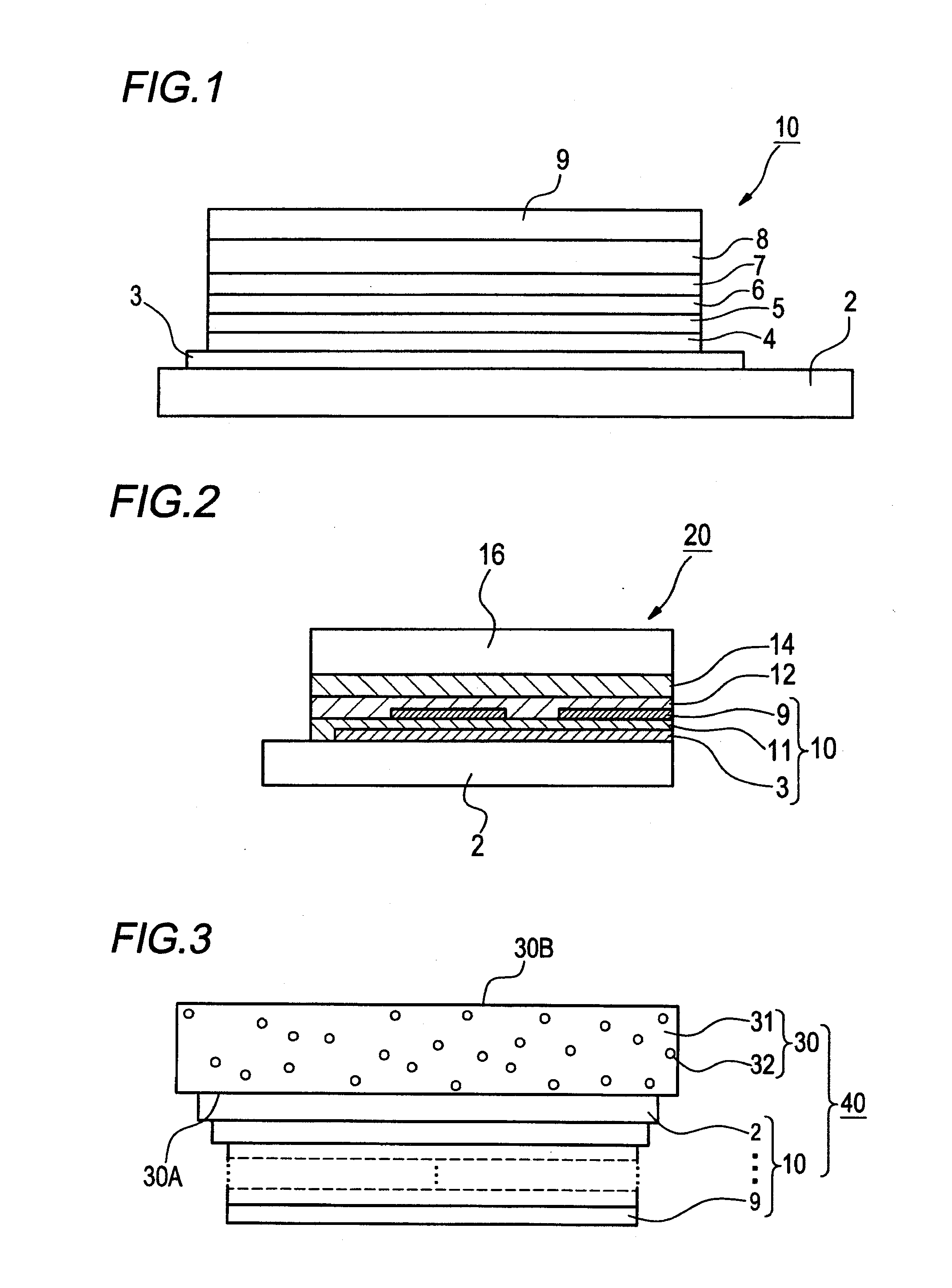
[0495]An indium tin oxide (ITO) film-coated glass substrate having an area of 2.5 square centimeters and a thickness of 0.5 mm (made by GEOMATEC Corporation, surface resistivity: 10 Ω / sq) was placed in a cleaning vessel and subjected to ultrasonic cleaning in 2-propanol, and the thus cleaned substrate is further subjected to UV-ozone treatment of 30 minutes. Onto this transparent anode (ITO film), the following organic layers (organic compound layers) were evaporated in sequence by using a vacuum evaporation method.

[0496]The evaporation speed in each of Examples relating to the invention was 0.2 nm / sec unless otherwise specified. Evaporation speed measurements were made with a quartz resonator. And the following film thicknesses were also measured with a quartz resonator.

[0497]The ITO substrate cleaned in the foregoing manner was placed in a vacuum evaporator, and copper phthalocyanine was evaporated onto this substrate in the form of a 10 nm-thick film (first layer). Onto the first...

examples 1-2 and 1-3

, and Comparative Example 1-1

[0498]Devices of Examples 1-2 and 1-3 and a device of Comparative Example 1-1 were made in the same manner as the device of Example 1-1, except that the method used for preparing Exemplified Compound 63 in Example 1-1 was changed to the methods entered in Table 1, respectively. A direct-current constant voltage was applied to these devices, respectively, through the use of Source Measure Unit 2400 made by TOYO Corporation, and thereby the devices produced luminescence in colors originating in the light emitting materials incorporated, respectively.

[0499]Each of the organic EL devices made in Examples 1-1 to 1-3 and Comparative Example 1-1, respectively, was mounted in an emission spectrum measuring system made by Shimadzu Corporation (ELS-1500), and thereon measurement of an impressed voltage at which the emission spectral intensity of each device reached 1,000 cd / m2 was made.

[0500]Each of the organic EL devices made in Examples 1-1 to 1-3 and Comparativ...


PUM


Abstract

To provide methods of forming fluorescence-producing organometallic complexes which can ensure high durability when used in organic electroluminescence devices. For example, a compound 106 is prepared in accordance with the following reaction scheme.

Description

CROSS-REFERENCE TO RELATED APPLICATION(S)[0001]The present application claims priority from Japanese Patent Application Nos. 2009-201148 filed on Aug. 31, 2009, and 2010-076448 filed on Mar. 29, 2010, the entire content of which is incorporated herein by reference.BACKGROUND[0002]1. Field[0003]The present invention relates to methods of forming metal complex compounds, and to organic electroluminescence devices. More specifically, the invention relates to methods of forming fluorescent organic metal complexes, especially methods of forming fluorescent organic metal complexes for use in organic electroluminescence devices (light emitting devices, or EL devices), and with organic electroluminescence devices made by using such the organic metal complexes.[0004]2. Description of the Related Art[0005]In recent years, organic metal complexes have received attention as functional materials such as new display materials, memory materials, photosensitizing dyes and chemical sensor dyes. By u...

Claims


Application Information

Patent Timeline
IPC IPC(8): H01J1/63C07F15/00
CPCC07F15/0086C09K11/06C09K2211/1029C09K2211/1044C09K2211/1059C09K2211/185H05B33/14H05B33/20C07F15/0033H10K85/346H10K85/324H10K85/342H10K50/11H10K2102/103H10K50/18H10K50/17H10K50/15H10K50/16H10K50/171C09K2211/1007
Inventor FUKUZAKI, EIJI
Owner UDC IRELAND
Learn More