
Wavelocker for Improving Laser Wavelength Accuracy in WDM Networks

a laser wavelength accuracy and wavelength lock technology, applied in the field of optical communication, can solve the problems of increasing the cost of high-speed optics with the line bit rate, limiting the implementation of specific protocols, and unable to achieve the desired routing of these four client circuits, so as to achieve the effect of maintaining full visibility of the deployed channel and available bandwidth, reducing the cost overhead, and facilitating map services

Inactive Publication Date: 2011-06-09
VELLO SYST +1
View PDF8 Cites 119 Cited by
  • Summary
  • Abstract
  • Description
  • Claims
  • Application Information

AI Technical Summary

Benefits of technology

[0087]Novel techniques are employed (at the subchannel level / layer) to facilitate the desired optical routing, switching, concatenation and protection of the client circuits mapped to these subchannels across the nodes of a WDM network, resulting in a significant increase in the number of optical circuits in a fiber, and thus in the overall bandwidth and spectral efficiency of the WDM network.
[0088]Network architectures and subchannel transponders, muxponders and crossponders are disclosed that map client signals to a set of subchannel frequencies. In one embodiment, these architectures employ two levels of frequency mapping and two cascaded optical filters (one for filtering WDM channels and one for filtering subchannels). Additional methods of multiplexing channels and subchannels by means of polarization multiplexing and related feedback control electronic systems are also disclosed. Selectively mapping client signals to a subset of the subchannels facilitates network functions such as broadcast and select transmission, arbitrary concatenation, optical source routing, shared optical protection, and simplified network reconfiguration at a significantly lower cost than is required for currently deployed WDM networks.
[0093]Multilayer routing protocols are disclosed that enable network operators to easily map services to available bandwidth, while maintaining full visibility of the deployed channels and available bandwidth. Means for adiabatically adjusting the network capacity are described to ensure minimal planned or indeliberate service interruption. A novel OSC routing protocol is described to manage such a network with minimal cost overhead. Other embodiments are disclosed that enable networks to be upgraded from being ITU-channel based to subchannel based.

Problems solved by technology

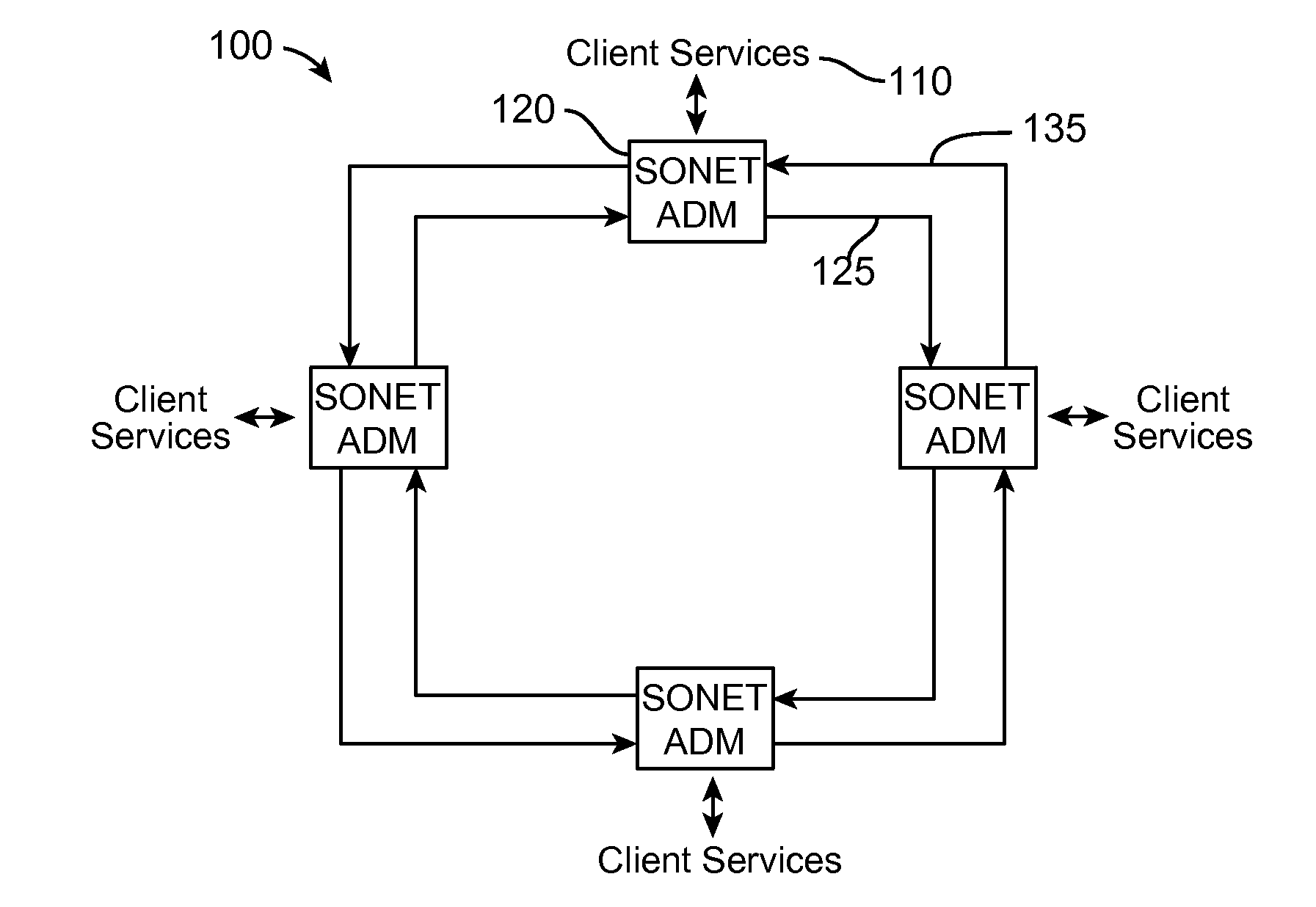
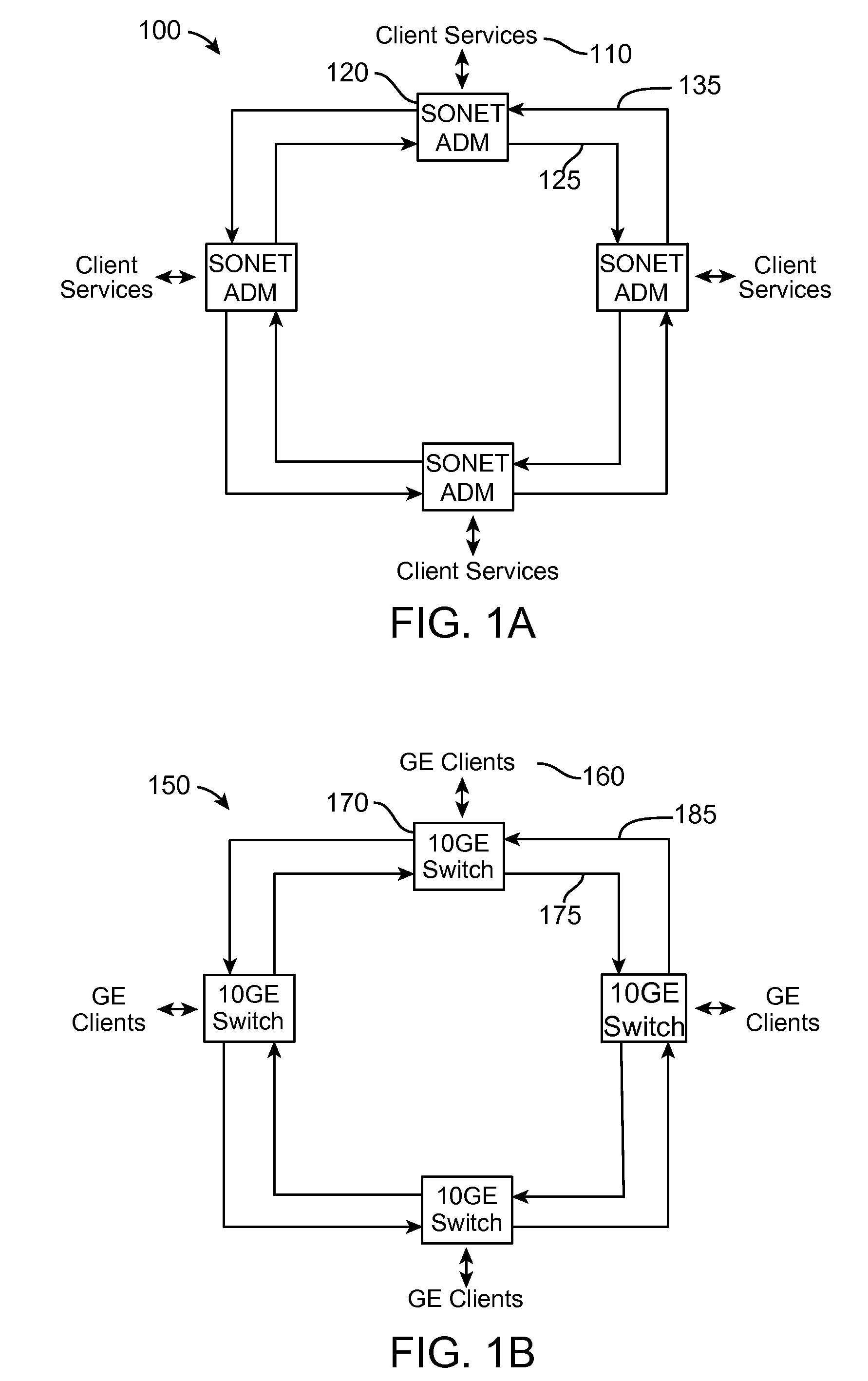
Yet, unless an entire channel is free to enable all four client circuits to continue propagating together to a subsequent node on the network, the desired routing of these four client circuits may not be achievable without some mechanism for dynamically rerouting individual client circuits, independent of one another, across different fiber channels.
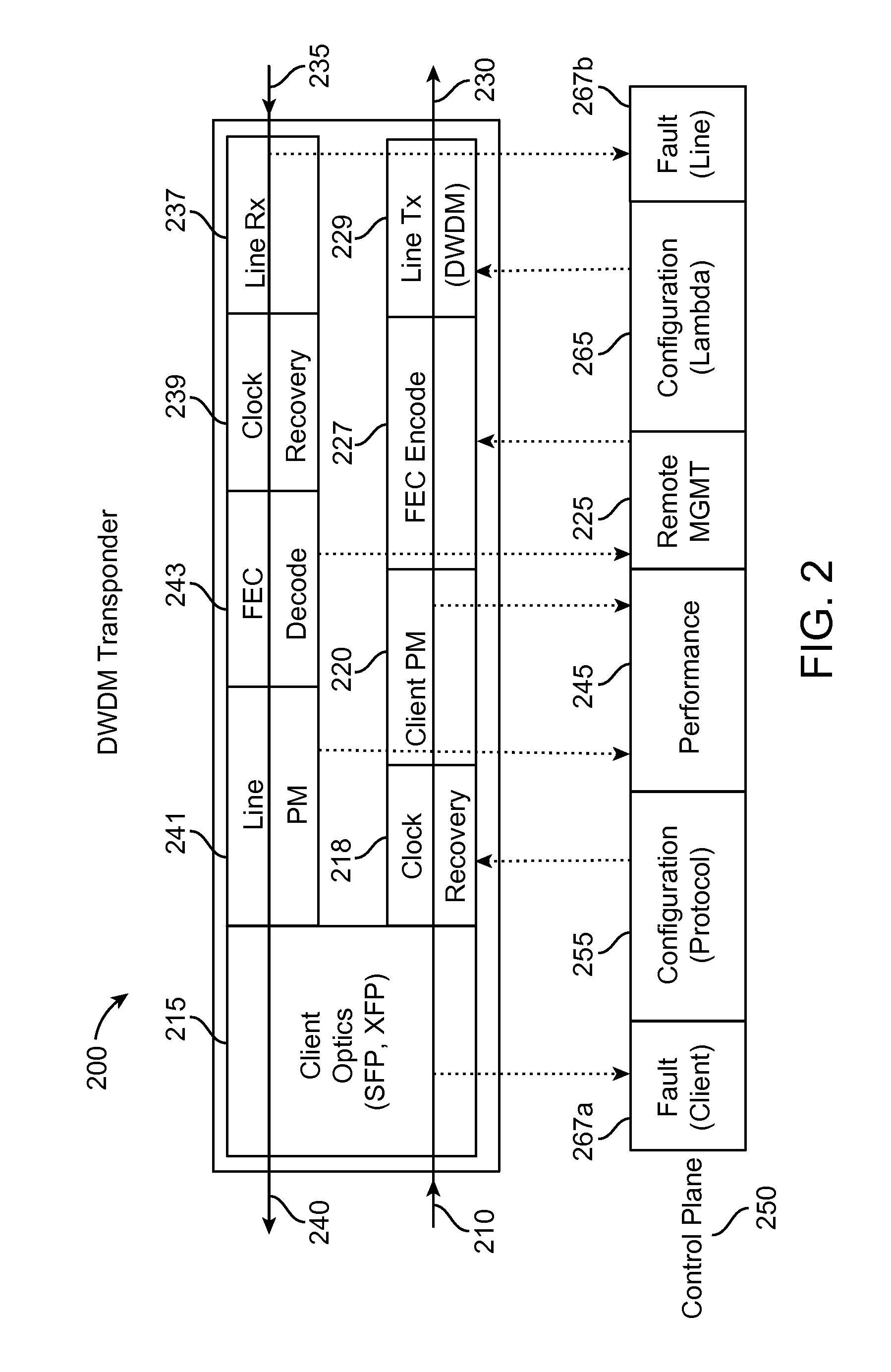
Although the transponder 200 and muxponder 300 can be designed to transmit signals from different sources and with different bit rates, the hardware limitations and costs typically limit the implementation to a specific set of protocols.
The cost of the high-speed optics increases with the line bit rate so that vendors typically partition their products into different data rates such as 2.5 Gb / s, 10 Gb / s, 40 Gb / s, and 100 Gb / s.
The number of channels on the ITU grid is limited in most applications to the gain range available from erbium-doped fiber amplifiers (EDFAs).
To date, broadcast and select architectures have been limited by the number of channels supported by the optical demultiplexers.
Note that in either configuration of FIG. 5 or FIG. 6, the drop filter may not provide enough isolation on the passthrough path.
All optical filters have a useable passband less than ideal because of the finite slope of the filter passband.
Because of human error in manually adding the fiber patchcords (802a and 802b, and 804a and 804b) between the modules (add / drop modules 810 and 820, and transponders / muxponders 830 and 840), this partitioning can lead to misconnections of the fiber patchcords.
These mistaken connections may be difficult to detect, especially if there are two redundant paths between the terminals.
Tracing optical connections can be difficult in this scenario because the multiplexers, amplifiers, and other equipment may not have means to independently detect each incident channel.
But this method requires dedicated hardware at all monitoring points and it cannot detect third-party signals (i.e., “alien” signals that are generated by other equipment vendors, but which may be inserted into a WDM network as long as they are on the same ITU channel plan and do not interfere with other signals).
However, getting a full view of the network may require many of these and thus add considerable cost [see, eg, U.S. Pat. No. 7,002,697].
Guaranteeing the performance and determining the link budget for an installed network can be costly because determining the factors listed above may require expensive test equipment.
Furthermore, the tests may have to be run while the network is out of service so that changes over time after a network is installed cannot be detected.
Although shared optical protection offers significant bandwidth savings, its practicality is limited by the requirement of maintaining link budget rules for all possible protection paths.
WSS-based filters are currently much more expensive than fixed filters.
Ring interconnections can also be done with fixed optical filters, but those connections cannot be reconfigured remotely, so that network upgrades require technicians to go to the interconnecting sites and manually reconfigure the connections on the fixed filters.
Furthermore, many deployed optical networks have difficulty managing WDM traffic through on these paths so that the traffic may be segmented by electro-optical conversions at the intersecting nodes (A, B, F).
These electro-optical conversions add cost and complexity to the network while reducing reliability.
Installing dispersion compensation and amplifiers to compensate for their loss can be very disruptive since operators may have to break the traffic multiple times and at multiple sites.
Even with the ability to upgrade the capacity without installing additional dispersion compensators, adding or removing channels from a DWDM network can be disruptive to the live traffic because the channels can propagate through shared components such as amplifiers and attenuators that act upon the total power.
This drop in power could cause bit errors.
Adding the filters to add and drop the OSC channel add loss and cost to the network.
Although VLSI technology has enabled very large switching matrices in electronics [see, eg, U.S. Pat. No. 6,714,537], the switch size is still limited at very high bandwidths.
Note that this architecture shown in ring 1300 can be costly because O-E-O conversions may be required at each switch and bandwidth is being used to send traffic to and from the centralized switches.
Also, the cost of such switches increases with the number of ports and bandwidth per port so that a network based on switches that support traffic bandwidth >1 Tb / s combined with high bandwidth WDM links can have a very high cost.
Furthermore, an all-optical switch can have high loss, so that it requires expensive optical amplifiers to compensate for the loss.
For example, transponders do not necessarily provide electrical mapping, multiplexing, or protection switching.

Method used


Image

  • Wavelocker for Improving Laser Wavelength Accuracy in WDM Networks
  • Wavelocker for Improving Laser Wavelength Accuracy in WDM Networks
  • Wavelocker for Improving Laser Wavelength Accuracy in WDM Networks

Examples


embodiment 1

Beating of Two Lasers, Both at Fixed Frequencies

[0542]The simplest example of a frequency beating phenomenon may be described as follows. Assume that two laser beams of equal optical power and aligned polarizations are launched into the Polarization Maintaining (PM) optical fiber. Assume that the first laser is tuned to an optical frequency fo (oscillator) and the second laser is tuned to an optical frequency fs (signal) so that the frequencies differ by:

fRF=|fs−fo, (e.g. fRF=500 MHz);

[0543]Also assume that the linewidth of both lasers (Δfo-FWHM for the oscillator and Δfs-FWHM for the signal laser) are approximately the same and equal to:

ΔfFWHM=Δfo-FWHM=Δfs-FWHM;

[0544]and substantially smaller than fRF (e.g. ΔfFWHM=1 MHz).

N.B. sub-index “FWHM” stands for a “Full Width at Half Maximum” linewidth definition.

[0545]When the combined light of both lasers is detected by a photodetector with an electrical bandwidth larger than fRF, but much smaller than the frequencies of optical light fs ...

embodiment 2

Beating a DWDM Signal Laser at Fixed Frequency (with a Narrow Optical Carrier) with an Oscillator Laser with a Scanned Frequency

[0548]We now expand the first example to a more practical beating system suitable for DWDM applications. We now assume that in addition to all the conditions described above, the frequency of the reference laser, fo, is tuned from fs−fRF−ε to fs+fRF+ε, where ε is much larger than ΔfFWHM. See graph 8400 in FIG. 84 which illustrates this case.

[0549]While scanning the oscillator laser within the said range, the amplitude of the RFDBS output would show two strong peaks (maxima substantially higher than zero) at frequencies of the oscillator laser approximately equal to fo=fs−fRF and fo=fs+fRF, where the equal sign means an equality within + / −ΔfRF-FWHM or a few times + / −ΔfRF-FWHM.

[0550]In this example the RFDBS output is maximized when the oscillator frequencies are set to fo-left and fo-right.

[0551]By analyzing the frequency positions of two RFDBS output peaks ...

embodiment 3

Beating a DWDM Signal Laser at a Fixed Frequency (with a Broad Spectrum) with a Scanned in Frequency Oscillator Laser

[0553]For DWDM modulation formats such as duo-binary (DB), Quadrature-Phase-Shifted-Keying (QPSK) or Differential-Quadrature-Phase-Shifted-Keying(DQPSK), the optical carrier is substantially or totally suppressed and the signal laser spectrum is broad (e.g. several or several tens of GHz) as shown in graph 8500 in FIG. 85.

[0554]In this case, the RFDBS Output signal would in general show two broad spectral lines or more. They can be distinct and separated in spectrum as in FIG. 85 or overlap to some or large extent depending on the choice of detection parameters such as fRF, ΔfRF-FWHM, Δfo-FWHM, bandwidth of the photodetector, gain and integration constant of the processing circuit, intensity of both signal and oscillator lasers and other design parameters for a particular implementation.

[0555]In one embodiment, the RFDBS signal spectrum, namely the RFDBS output versus...


PUM


Abstract

The present invention includes novel techniques, apparatus, and systems for optical WDM communications. Various wavelocker apparatus and methods are disclosed that measure the frequency offsets between signal lasers and reference lasers. The measured offsets are used to adjust the signal laser frequencies to meet their target frequencies. The absolute accuracy of the reference laser frequency is improved by measuring the absorption of the reference laser by a gas cell with known fixed absorption lines versus the reference laser frequency. Apparatus and methods are disclosed to cover scenarios in which the reference laser polarization is aligned with the signal lasers, as well as those in which the reference laser polarization is not aligned with the signal lasers. The wavelocker apparatus may or may not be located at the same network site as the signal lasers.

Description

CROSS REFERENCE TO RELATED APPLICATIONS[0001]This application claims the benefit, pursuant to 35 U.S.C. §119(e), of U.S. Provisional Patent Application No. 61 / 267,786, filed Dec. 8, 2009, entitled “Subchannel Photonic Routing, Switching and Protection with Simplified Upgrades of WDM Optical Networks,” which is hereby incorporated by reference in its entirety.I. BACKGROUND[0002]A. Field of Art[0003]This application relates generally to optical communications based on optical wavelength-division multiplexing (WDM), and in particular to subchannel routing, switching, and protection, along with related techniques that facilitate network upgrades and reuse of legacy equipment.[0004]B. Description of Related Art[0005]1. Overview[0006]Optical WDM communication systems transmit multiple optical channels at different WDM carrier wavelengths through a single fiber. The infrastructures of many deployed optical fiber networks today are based on 10 Gb / s per channel. As the demand for higher tran...

Claims


Application Information

Patent Timeline
Patent Type & Authority Applications(United States)
IPC IPC(8): H04B10/08H04B10/2581H04L45/28H04L45/50
CPCH04B10/572H04J14/0287H04J14/0201H04J14/02H04B10/0793H04J14/0293H04L45/28H04L45/50H04Q11/0066H04Q2011/0081
Inventor MYSLINSKI, PIOTRBARNARD, CHRIS WILHELM
Owner VELLO SYST
Learn More