
Flux addition as a filter conditioner

a filter conditioner and filter technology, applied in the direction of combustible gas production, combustible gas purification/modification, separation processes, etc., can solve the problems of reducing the permeability of elements to gas, restricting the passage of elements to synthesis gas, and affecting the efficiency of gasification systems, so as to increase the efficiency of gasification processes and systems, prevent infiltration, and increase the operational efficiency of particle filtration systems

Active Publication Date: 2011-06-23
LUMMUS TECH INC
View PDF25 Cites 11 Cited by
  • Summary
  • Abstract
  • Description
  • Claims
  • Application Information

AI Technical Summary

Benefits of technology

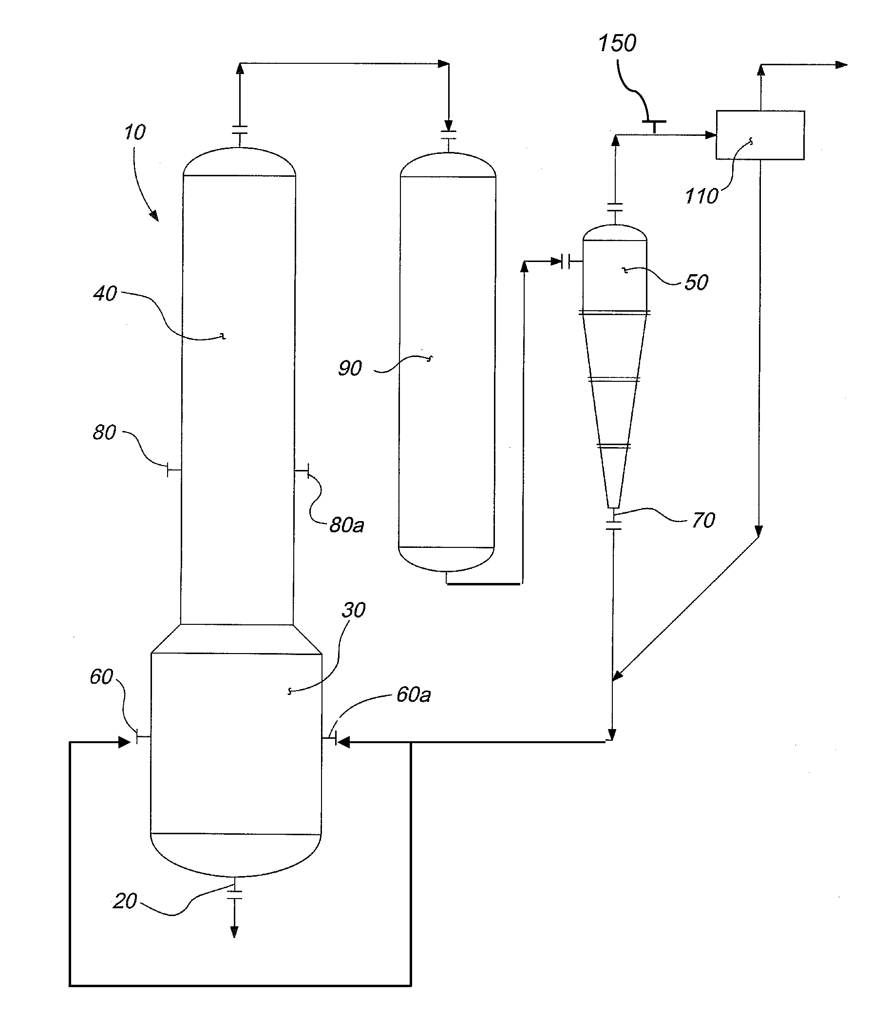
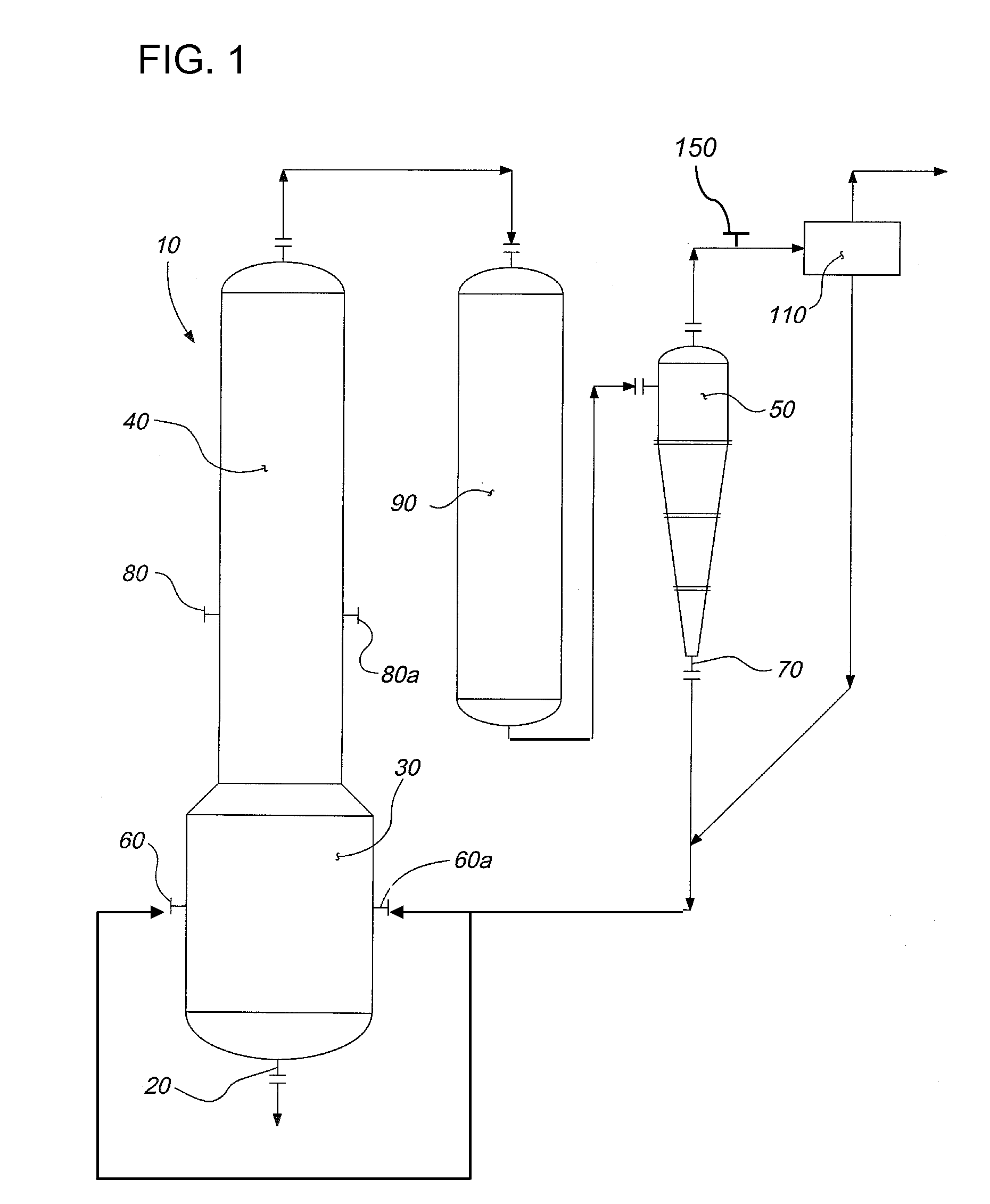
[0008]The present invention relates to improvements that increase the efficiency of gasification processes and systems. More specifically, certain embodiments increase the operational efficiency of the particle filtration system by preventing infiltration of char particles too deeply into the pores of filter elements. This, in turn, slows the rate of increase in differential pressure across the filter elements, thereby extending filter element lifespan. Certain embodiments additionally improve the efficiency of feedstock addition to the gasification reactor by eliminating the need to premix fluxing agent with the carbonaceous feedstock.
[0009]These improvements are achieved through the addition of a selectively-sized, coarse fluxing agent into the raw synthesis gas stream immediately upstream from the particle filtering device. The material composition and size range of the added fluxing agent particles is adjusted to properly condition the filter elements, wherein conditioning involves the deposition of a thin layer of fluxing agent particles onto the filter that maintains the permeability of the filter to synthesis gas. Relatively coarse flux particles are used for filter conditioning because these particles predominantly accumulate at, or near the surface of, the filter matrix during conditioning of the filter element, thereby inhibiting subsequent deep penetration of the filter matrix by smaller particles of char. The char particles instead accumulate predominantly outside of the filter elements as filter cake, thereby being more easily dislodged by periodic back-pulsing events. The overall benefit of using this strategy to condition the filter elements is that it slows the rate of increase in differential pressure across the filter elements, thereby extending filter element lifespan.
[0010]Following its function in conditioning the filter elements of the particle filtration unit, at least a portion of the fluxing agent is dislodged from the filter elements with each back-pulsing event along with at least a portion of the accumulated filter cake. The fluxing agent and removed filter cake then fall by force of gravity to a bin located at the bottom of the particle filtration unit, and this mixture is then recycled to the first stage of the gasifier. The recycling step increases the overall conversion efficiency of the carbonaceous feedstock, while simultaneously providing a novel mechanism for introducing fluxing agent into the gasification reactor.
[0011]A common practice is to mix fluxing agent with carbonaceous feedstock prior to adding the resulting mixture to the gasifier. However, this dilutes the feedstock, thereby reducing the maximum rate at which carbonaceous feedstock can be fed to the gasification reactor. In the current disclosure, the fluxing agent instead enters the gasification reactor along with the recycled char and ash collected by the particulate removal system. Thus, the carbonaceous feedstock added to the first stage of the reactor is not diluted by fluxing agent, which increases the efficiency of the overall gasification process. The material composition of the fluxing agent to be added can be adjusted as needed to adjust the melting point and viscosity of the molten slag at the bottom of the first stage of the gasifier, thereby assisting in the proper drainage of molten slag from the gasifier.
[0013]Certain additional embodiments of the invention comprise an improved process for gasification of a carbonaceous material, comprising the following steps: a) providing a gasification reactor comprising a first and second stage, wherein said reactor converts carbonaceous feedstock to produce a mixture product comprising a first gaseous product stream and a solid particulate stream, wherein said first gaseous product stream comprises H2 and CO, and wherein said solid particulate stream comprises char, b) passing said mixture product through an initial separating device, whereby a majority of said char is removed from said gaseous product stream, c) introducing a coarse particulate fluxing agent into the gaseous product stream downstream from said initial separating device, d) providing a particle filtration unit comprising a plurality of filter elements downstream from the point of introduction of said coarse particulate fluxing agent, e) depositing a thin layer of the fluxing agent onto and within the pores the filter elements, thereby conditioning the filter elements and decreasing the subsequent permeability of the filter elements to entrained char particles, while maximizing permeability to synthesis gas, f) periodically removing a mixture comprising filter-cake from the filter elements by back-pulsing, wherein said filter-cake comprises coarse particulate fluxing agent and char, and g) forming a mixture comprising the removed char of step b) and the removed filter-cake of step f), then routing this mixture to the gasification reactor of step a). In certain embodiments, the process may further comprise a step of passing said mixture product of step a) into a heat recovery zone prior to step b), wherein said heat recovery zone comprises a heat recovery device selected from a group consisting of radiant heat type boiler, water tube boiler, fire tube boiler and combinations thereof. In certain embodiments, said coarse particulate fluxing agent decreases the melting point and viscosity of molten slag in the gasification reactor, thereby assisting in the removal of the molten slag from the reactor. In certain embodiments, said coarse particulate fluxing agent may comprise limestone, magnesium oxide, clay, silicates, borates, flyash, slag, and mixtures thereof.

Problems solved by technology

However, the functional efficiency of this system can be hampered by the accumulation of fine particles of char within the pores of the filter elements.
These fine particles often become lodged deeply within filter element pores, which restricts the permeability of the elements to the passage of synthesis gas.
Accumulation of fine particles on the elements over time leads to the formation of a “filter cake” that further decreases the permeability of the elements to gas.
However, small particles that are trapped within the filter element pores are often not effectively dislodged by back-pulsing.
Infiltration of these particles decreases the lifespan of the filter elements, and hampers routine operation of the particulate filtration device.
Current conditioning protocols require a decrease in the input rate of raw synthesis gas to the filtration unit until this initial thin layer of filter cake accumulates, and this results in decreased operating availability of the particle filtration unit.
However, this reduces the overall efficiency of the gasification process both by requiring a mixing step, and also by reducing the maximum rate at which carbonaceous feedstock can be added to the gasifier.

Method used


Image

  • Flux addition as a filter conditioner
  • Flux addition as a filter conditioner
  • Flux addition as a filter conditioner

Examples


example 1

Hypothetical Example 1

[0046]The following example is not intended to limit the scope of the invention, but rather, to illustrate certain features of one embodiment. A mixture of kaolin clay and limestone with an average particle size of 15 microns is injected into the raw synthesis gas stream downstream of the cyclone (initial separating device) and upstream of the particle filtration unit. The average size of the remaining entrained char particulates downstream of the cyclone is typically 1-2 microns. The coarse particle size of the additive prevents the fine submicron char particles from being lodged and embedded in the pore of the filter, thereby causing plugging of the filter. The kaolin and limestone particles simultaneously may also capture and scavenge certain trace contaminants or volatile metals, such as, but not limited to, arsenic and germanium. The char, kaolin, and limestone mixture, after being separated by the filter from the syngas stream, is transported and injected...


PUM

PropertyMeasurementUnit
sizeaaaaaaaaaa
temperatureaaaaaaaaaa

Abstract

Improvements in a gasification system and process for gasifying carbonaceous feedstock with improved energy efficiency. Improved methods and systems for more efficient removal of particulates from a raw synthesis gas while simultaneously providing a novel mechanism for fluxing agent addition to the gasification reactor. A conditioning agent, in the form of coarse fluxing agent particles, is added to the raw synthesis gas upstream from the particle filtration unit. The conditioning agent allows more rapid turnaround of the filtration unit following filter element replacement, extend filter life, facilitates the removal of filter cake from the particle filters, and combines with removed filter cake for recycling to the gasifier. Addition of fluxing agent via this route eliminates the need to premix fluxing agent with the carbonaceous feedstock, thereby maximizing the rate of feedstock addition to the gasification reactor.

Description

FIELD OF THE DISCLOSURE[0001]The present invention relates generally to an improvements in the conversion of solid or liquid carbonaceous feedstock into desirable gaseous products such as synthesis gas. More specifically, the present invention relates to improvements in the removal of entrained particulate matter from raw synthesis gas, as well as improvements in the addition of fluxing agent to a gasification reactor.BACKGROUND OF THE DISCLOSURE[0002]Synthesis gas is a fuel for power generation as well as an important intermediate feedstock for producing chemicals such as hydrogen, methanol, ammonia, substitute natural gas or synthetic transportation oil. Three basic types of systems and processes have been developed for the production of synthesis gas through the gasification of carbonaceous materials. They are: (1) fixed-bed gasification, (2) fluidized-bed gasification, and (3) suspension or entrainment gasification.[0003]The hot raw synthesis gas exiting the gasifier contains en...

Claims


Application Information

Patent Timeline
Patent Type & Authority Applications(United States)
IPC IPC(8): C10J3/46B01J8/00C01B32/40
CPCC10J3/485C10J3/721C10J3/84C10J3/86B01D29/66C10K1/026C10J2300/0993C10J2300/0996C10J2300/1807C10K1/024
Inventor TROXCLAIR, EMILE J.
Owner LUMMUS TECH INC
Learn More