Composition for making transparent conductive coating based on nanoparticle dispersion

a technology of nanoparticles and conductive coatings, applied in the direction of conductive materials, non-metal conductors, organic conductors, etc., can solve the problems of complex apparatuses having vacuum systems, poor productivity, and exceptional high cos

Inactive Publication Date: 2011-08-11
TECONA TECH
View PDF2 Cites 22 Cited by
  • Summary
  • Abstract
  • Description
  • Claims
  • Application Information

AI Technical Summary

Benefits of technology

It is further in the scope of the present invention wherein the foam (or bubble-in-water dispersion or ink) is formed...

Problems solved by technology

CVD or PVD produces a uniform coated film with good transparency and conductivity; however, it requires a complicated apparatus having a vacuum system and has poor productivity.
It is exceptional expensive because of the use of vacuum chamber.
It also requires subtractive patterning techniques, such as photolithography, to form highly conductive pattern, which are expensive, wasteful, and batch-oriented processes.
The limited supply and high price of indium along with the characteristic delamination/fracture observed upon flexion make ITO unsuitable for the next generation of solar panels and display technologies.
Other metal oxides, such as antimony-tin oxide (ATO), aluminum doped zinc oxide (AZO) and fluorine doped tin oxide (FTO) can also be used as cheaper alternative to ITO, but usually with inferior property, either l...

Method used


Image

  • Composition for making transparent conductive coating based on nanoparticle dispersion
  • Composition for making transparent conductive coating based on nanoparticle dispersion
  • Composition for making transparent conductive coating based on nanoparticle dispersion

Examples


example 1

Transparent Conductive Coating on Glass

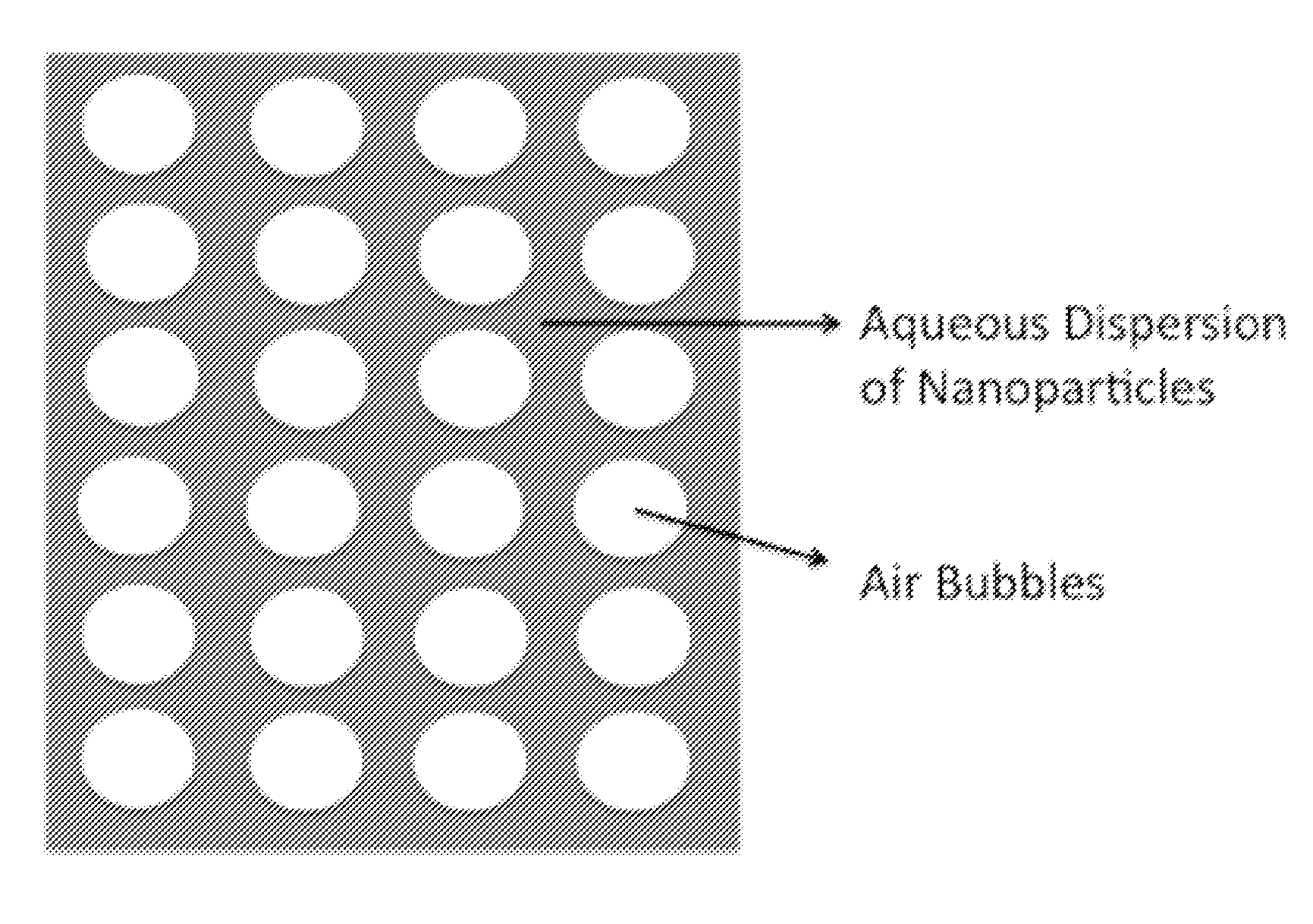
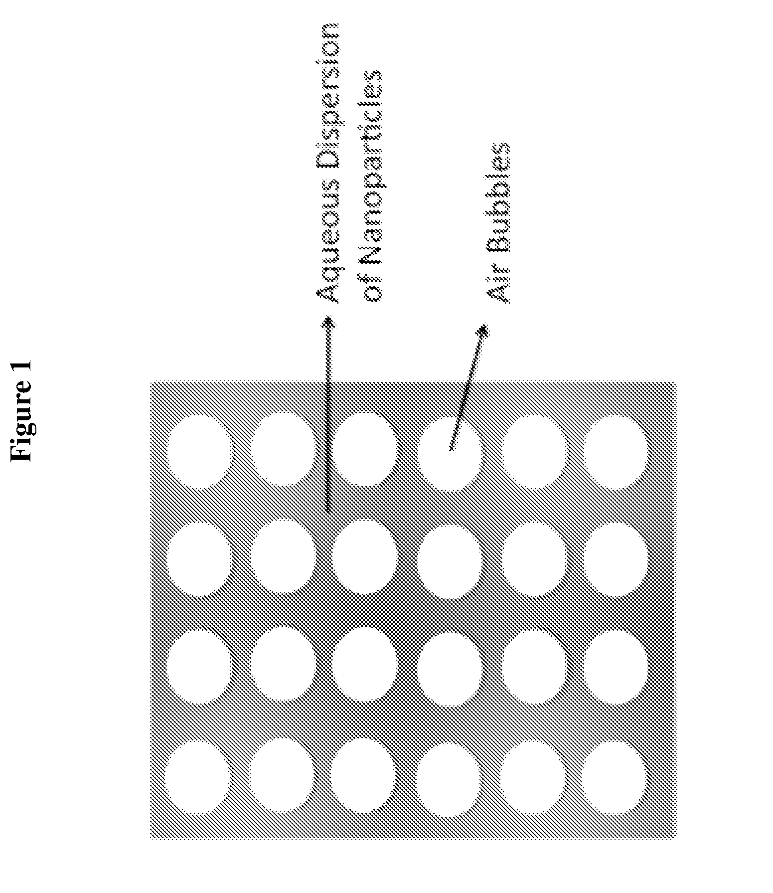
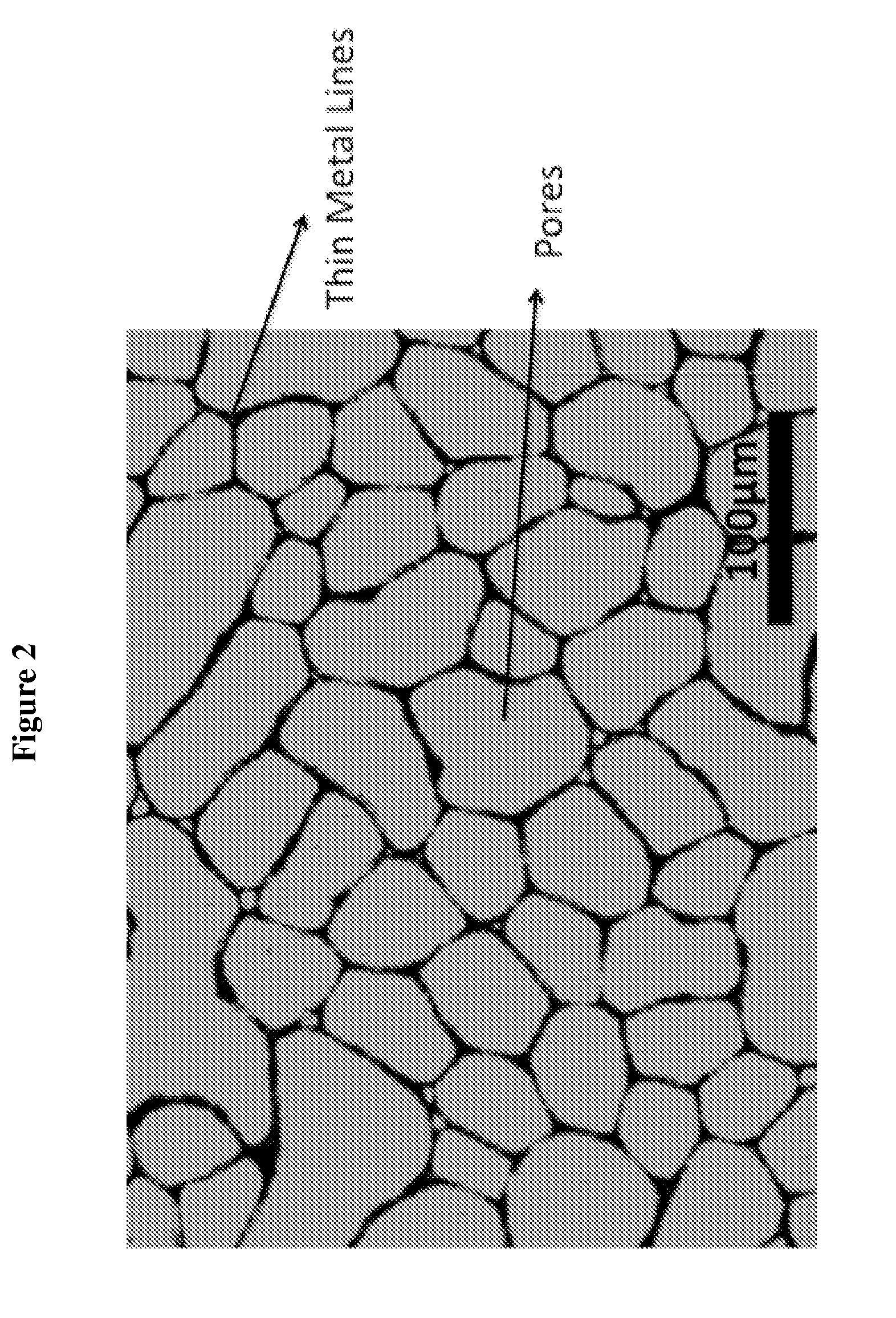
Admix metal nanoparticles (silver nanoparticles, average particle size 80 nm), 10 g; water, 42.2 g; a foam forming chemical (Macare® G-2C), 2.2 g; a viscosity modifier (cocamidopropyl betaine), 0.28 g; a surfactant (Synperonic 91 / 6), 0.55 g; an adhesion promoter (Cartacoat B750), 0.28 g. Then homogenizing the obtained solution by ultrasonic energy (ultrasonic horn) for 2 minutes until a foam (bubble-in-water dispersion) formed. Spray the obtained homogenized foam solution onto the surface of glass by ultrasonic spray nozzle. This formulation gave a good developed chickwire-like network with pore sizes of 30 μm to 100 μm and Ag lines with 2 μm to 5 μm width. Reference is made now to FIG. 2, presenting a view taken by a means of a light microscope showing the chickwire-like network on a glass surface as obtained by the method as described in Example 1. This film has over 80% transparency in the range of 400 nm to 700 nm, as shown in FIG. 6, measu...

example 2

Transparent Conductive Coating on PET

Admix metal nanoparticles (silver nanoparticles, average particle size 30 nm), 8 g; water, 38.3 g; a foam forming chemical (Masurf G-2C), 2.7 g; a secondary solvent (ethanol), 2.7 g; a viscosity modifier (glycerol), 0.27 g; a surfactant (Surfynol 465), 0.91 g; a humectant, 0.27 g; an adhesion promoter(arabinogalactan), 0.27 g. Then homogenizing the obtained solution by ultrasonic energy (ultrasonic horn) for 2 minutes until a foam (bubble-in-water dispersion) formed. Spray the obtained homogenized foam solution onto the surface of polyethylene terephthalate (PET) by ultrasonic spray nozzle. This formulation gave a good developed chickwire-like network with pore sizes of 20 μm to 120 μm and Ag lines with 2 μm to 10 μm width. Reference is made now to FIG. 3, presenting a view taken by a means of a light microscope showing the chickwire-like network on a PET surface as obtained by the method as described in Example 2. This film has over 75% transpar...


PUM


Abstract

The present invention is directed to a composition for preparing transparent conductive coating on transparent substrate by an environment friendly method. An aqueous foam dispersion containing metal nanoparticles can form a transparent film by spontaneous self-assembly, which becomes conductive after sintering. The foam formulation contains mainly water without any toxic organic solvent.

Description

FIELD OF THE INVENTIONThis invention is directed to compositions and methods of incorporating metal nanoparticles into aqueous foam formulation / inks and applying the inks onto substrates to form transparent conductive coating. The resulting transparent and conductive layers are useful for thin film solar cells, touch screens, thin film transistor-liquid crystal display (TFT-LCD), plasma displays, organic light emitting diodes (OLED), EMI shielding, electrical papers (E-papers), flexible displays and other applications where optical transparency and electrical conductivity are desired.BACKGROUND OF THE INVENTIONOptically transparent and electrically conductive films are widely used in many kinds of electronic devices, such as thin film solar cell, touch screen, TFT-LCD, OLED, E-papers, EMI shielding, flexible displays and other applications where transparency and conductivity are required at the same time. Industry standard transparent conductor is indium-tin-oxide (ITO) film, which ...

Claims


Application Information

Patent Timeline
IPC IPC(8): H01B1/12
CPCH01B1/16
Inventor SHI, WEILI
Owner TECONA TECH
Why Eureka
Try Eureka