
High energy density redox flow device

a redox flow and high energy density technology, applied in the field of high energy density redox flow devices, can solve the problems of reducing the energy and power density of the device, unable to sustain the charge imbalance, and limited current extraction rate,

Active Publication Date: 2011-08-18
MASSACHUSETTS INST OF TECH +2
View PDF82 Cites 242 Cited by
  • Summary
  • Abstract
  • Description
  • Claims
  • Application Information

AI Technical Summary

Benefits of technology

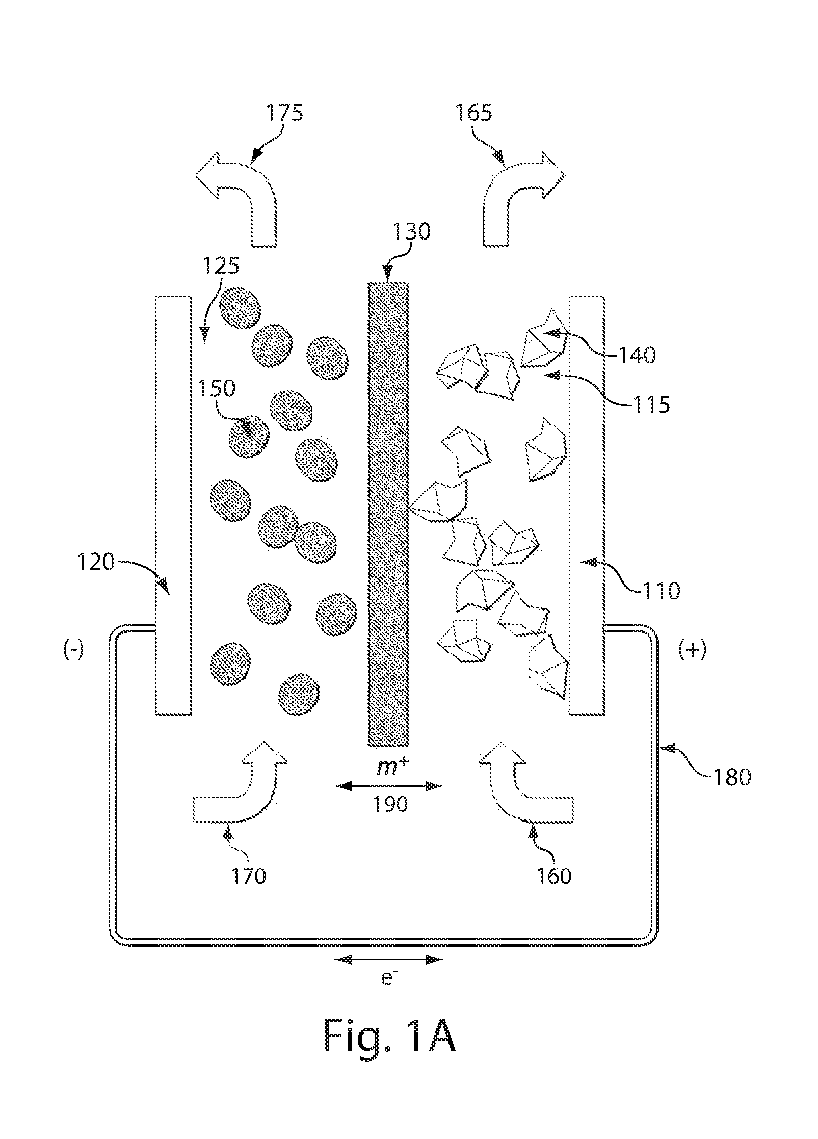
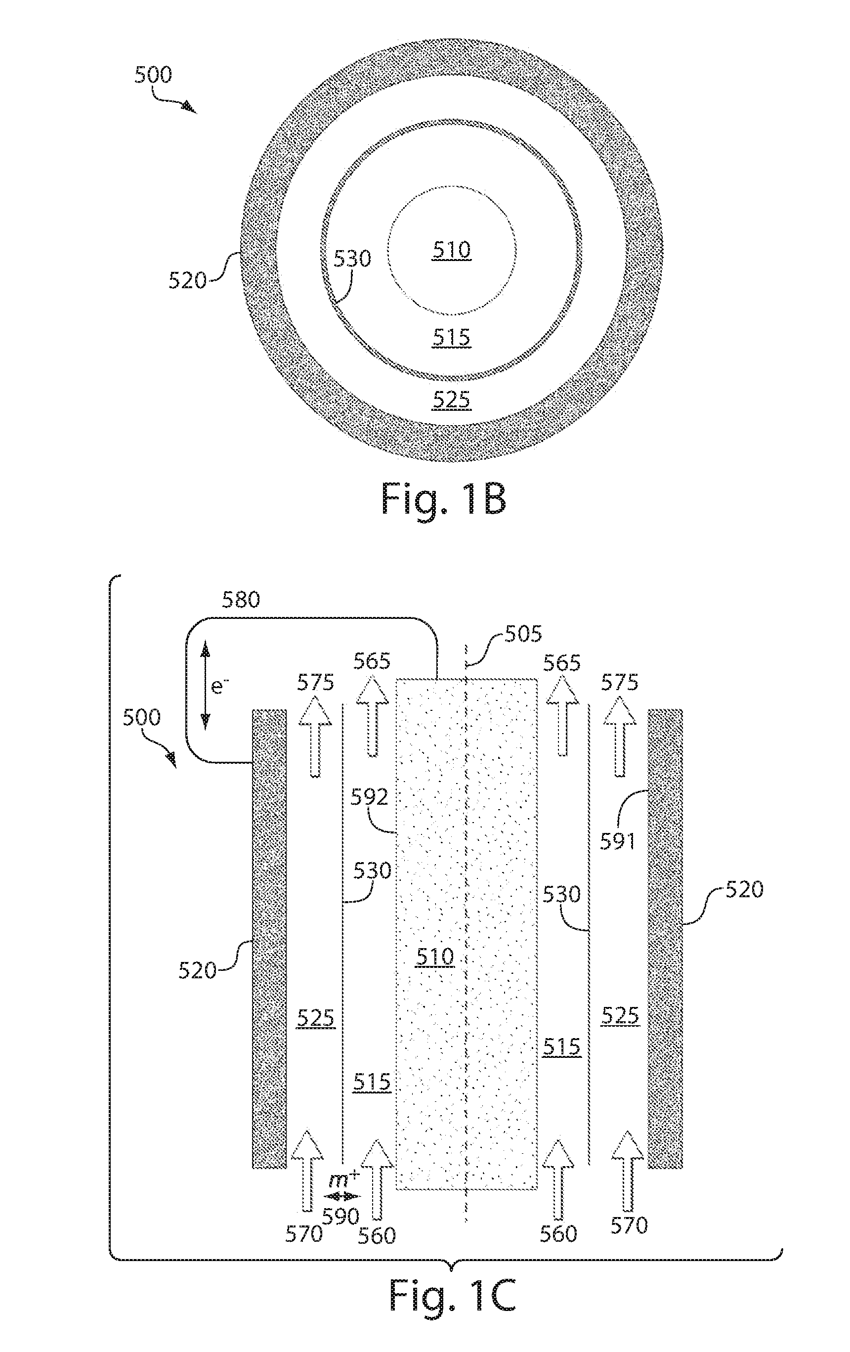
[0073]The energy storage systems described herein can provide a high enough specific energy to permit, for example, extended driving range for an electric vehicle, or provide a substantial improvement in specific energy or energy density over conventional redox batteries for stationary energy storage, including for example applications in grid services or storage of intermittent renewable energy sources such as wind and solar power.
[0076]In some embodiments, a source of acoustic energy for a redox flow energy storage device is provided. In some embodiments, the redox flow energy storage device comprises a positive electrode active material, a negative electrode active material, and an ion-permeable medium separating said positive and negative electrode active materials, wherein at least one of said positive and negative electrode active materials comprises a flowable ion-storing redox composition which is capable of taking up or releasing said ions during operation of the device, wherein the flowable ion-storing redox composition comprises a solid, and said source of acoustic energy is constructed and arranged to inhibit the accumulation of the solid within the redox flow energy storage device and / or to reduce the viscosity of the flowable ion-storing redox composition within the redox flow energy storage device.

Problems solved by technology

Because a charge imbalance cannot be sustained between the negative electrode and positive electrode, these two flow streams supply ions and electrons at the same rate.
In this case, non-energy storing elements of the device comprise a fixed volume or mass fraction of the device; thereby decreasing the device's energy and power density.
The rate at which current can be extracted is also limited by the distance over which cations can be conducted.
Thus, power requirements of static cells constrain the total capacity by limiting device length scales.
While redox flow batteries have many attractive features, including the fact that they can be built to almost any value of total charge capacity by increasing the size of the catholyte and anolyte reservoirs, one of their limitations is that their energy density, being in large part determined by the solubility of the metal ion redox couples in liquid solvents, is relatively low.
However, such measures which may be detrimental to other aspects of the cell operation, such as by increasing corrosion of cell components, storage vessels, and associated plumbing.
Furthermore, the extent to which metal ion solubilities may be increased is limited.

Method used


Image

  • High energy density redox flow device
  • High energy density redox flow device
  • High energy density redox flow device

Examples


example 1

Semi-Solid Lithium Redox Flow Battery

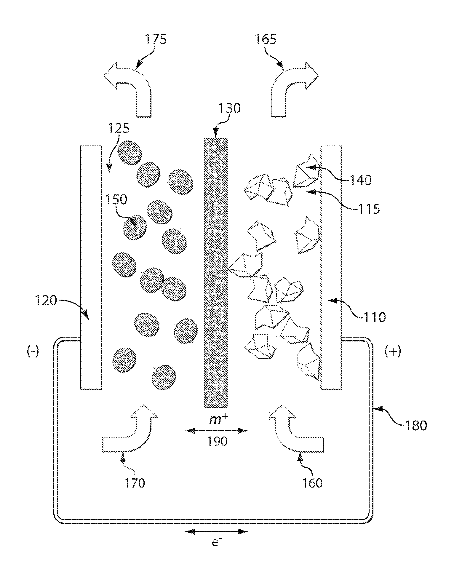
[0222]An exemplary redox flow cell 200 for a lithium system is shown in FIG. 2. In this example, the membrane 210 is a microporous membrane such as a polymer separator film (e.g., Celgard™ 2400) that prevents cathode particles 220 and anode particles 230 from crossing the membrane, or is a solid nonporous film of a lithium ion conductor. The negative and positive electrode current collectors 240, 250 are made of copper and aluminum, respectively. The negative electrode composition includes a graphite or hard carbon suspension. The positive electrode composition includes LiCoO2 or LiFePO4 as the redox active component. Carbon particulates are optionally added to the cathode or anode suspensions to improve the electronic conductivity of the suspensions. The solvent in which the positive and negative active material particles are suspended is an alkyl carbonate mixture and includes a dissolved lithium salt such as LiPF6. The positive electrode compo...

example 2

Semi-Solid Nickel Metal Hydride Redox Flow Battery

[0223]An exemplary redox flow cell for a nickel system is shown in FIG. 3. In this example, the membrane 310 is a microporous electrolyte-permeable membrane that prevents cathode particles 320 and anode particles 330 from crossing the membrane, or is a solid nonporous film of a proton ion conductor, such as Nafion. The negative and positive electrode current collectors 340, 350 are both made of carbon. The negative electrode composition includes a suspension of a hydrogen absorbing metal, M. The positive electrode composition includes NiOOH as the redox active component. Carbon particulates are optionally added to the cathode or anode suspensions to improve the electronic conductivity of the suspensions. The solvent in which the positive and negative active material particles are suspended is an aqueous solution containing a hydroxyl generating salt such as KOH. The positive electrode composition is stored in positive electrode stora...

example 3

Reference Electrode Monitored Redox Flow Battery

[0224]An exemplary redox flow battery using a reference electrode to optimize cell performance is shown in FIG. 4. The cell includes two membranes 410, 415. Reference electrodes 420, 425, 430 are positioned between the two membranes 410, 415 on a face opposite that of the electroactive zones 440, 445 where positive electrode redox flow composition 442 and negative electrode redox flow composition 447 flow, respectively. The cell also includes negative and positive current collectors 450, 460, respectively.

[0225]The potential at each reference electrode 420, 425 and 430 can be determined and are assigned a value of φ1, φ2 and φ3, respectively. The potentials at the working electrodes (current collectors) 450, 460 can also be determined and are assigned a value of W1 and W2, respectively. The potential differences of the cell components can be measured as follows:

(W1−W2)=cell voltage

(W2−φ3)=potential at cathode

(W1−φ3)=potential at anode

(...


PUM

PropertyMeasurementUnit
Volumeaaaaaaaaaa
Volumeaaaaaaaaaa
Volumeaaaaaaaaaa

Abstract

Redox flow devices are described in which at least one of the positive electrode or negative electrode-active materials is a semi-solid or is a condensed ion-storing electroactive material, and in which at least one of the electrode-active materials is transported to and from an assembly at which the electrochemical reaction occurs, producing electrical energy. The electronic conductivity of the semi-solid is increased by the addition of conductive particles to suspensions and / or via the surface modification of the solid in semi-solids (e.g., by coating the solid with a more electron conductive coating material to increase the power of the device). High energy density and high power redox flow devices are disclosed. The redox flow devices described herein can also include one or more inventive design features. In addition, inventive chemistries for use in redox flow devices are also described.

Description

RELATED APPLICATIONS[0001]This application is a continuation-in-part of U.S. patent application Ser. No. 12 / 484,113, entitled “High Energy Density Redox Flow Device,” filed Jun. 12, 2009, which claims priority under 35 U.S.C. §119(e) to U.S. Provisional Patent Application Ser. No. 61 / 060,972, entitled “High Energy Density Redox Flow Battery,” filed Jun. 12, 2008 and U.S. Provisional Patent Application Ser. No. 61 / 175,741, filed May 5, 2009, entitled “High Energy Density Redox Flow Battery.” This application also claims priority under 35 U.S.C. §119(e) to U.S. Provisional Patent Application Ser. No. 61 / 287,180, entitled “High Energy Density Redox Flow Device,” filed Dec. 16, 2009. Each of these applications is incorporated herein by reference in its entirety for all purposes.INCORPORATION BY REFERENCE[0002]All patents, patent applications and documents cited herein are hereby incorporated by reference in their entirety for all purposes.STATEMENT REGARDING FEDERALLY SPONSORED RESEARCH...

Claims


Application Information

Patent Timeline
IPC IPC(8): H01M4/36H01M14/00C01B21/24C01B21/22C01B31/24C01B21/36C07C69/96C07D307/33C07C43/11C07D307/06C07D317/12G01N33/00C01B32/60
CPCB60L11/1875B60L11/1898H01M8/188Y02T90/34Y02E60/528Y02T10/705H01M8/20B60L50/72B60L58/27Y02E60/50Y02T10/70Y02T90/40Y02P20/133
Inventor CHIANG, YET-MINGCARTER, W. CRAIGHO, BRYAN Y.DUDUTA, MIHAILIMTHONGKUL, PIMPA
Owner MASSACHUSETTS INST OF TECH
Learn More