Electromagnetic forming of metallic glasses using a capacitive discharge and magnetic field

a capacitive discharge and magnetic field technology, applied in metal-working equipment, welding/cutting media/materials, soldering media, etc., can solve the problems of limited use of early amorphous alloys as bulk objects and articles, limited size of early amorphous alloys, and inconvenient casting processes. achieve the effect of high permeability soft magnetic cor

Active Publication Date: 2012-01-12
CALIFORNIA INST OF TECH
View PDF14 Cites 45 Cited by
  • Summary
  • Abstract
  • Description
  • Claims
  • Application Information

AI Technical Summary

Problems solved by technology

As such, conventional casting processes were not suitable for such high cooling rates, and special casting processes such as melt spinning and planar flow casting were developed.
Due to the crystallization kinetics of those early alloys being substantially fast, extremely short time (on the order of 10−3 seconds or less) for heat extraction from the molten alloy were required to bypass crystallization, and thus early amorphous alloys were also limited in size in at least one dimension.
Because the critical cooling rate requirements for these amorphous alloys severely limited the size of parts made from amorphous alloys, the use of early amorphous alloys as bulk objects and articles was limited.
However, even though bulk-solidifying amorphous alloys provide some remedy to the fundamental deficiencies of solidification casting, and particularly to the die-casting and permanent mold casting processes, as discussed above, there are still issues which need to be addressed.
For example, presently available BMGs with large critical casting dimensions capable of making large bulk amorphous objects are limited to a few groups of alloy compositions based on a very narrow selection of metals, including Zr-based alloys with additions of Ti, Ni, Cu, Al and Be and Pd-based alloys with additions of Ni, Cu, and P, which are not necessarily optimized from either an engineering or cost perspective.
In addition, the current processing technology requires a great deal of expensive machinery to ensure appropriate processing conditions are created.
These modified die-casting machines can cost several hundreds of thousands of dollars per machine.
Because the “critical casting dimension” is correlated to the critical cooling rate, these conventional processes are not suitable for forming larger bulk objects and articles of a broader range of bulk-solidifying amorphous alloys.
Because the metal is fed into the die under high pressure and at high velocities, such as in high-pressure die-casting operation, the flow of the molten metal becomes prone to Rayleigh-Taylor instability.
This flow instability is characterized by a high Weber number, and is associated with the break-up of the flow front causing the formation of protruded seams and cells, which appear as cosmetic and structural micro-defects in cast parts.
Also, there is a tendency to form a shrinkage cavity or porosity along the centerline of the die-casting mold when unvitrified liquid is trapped inside a solid shell of vitrified metal.
None of these prior art methods teach how to uniformly heat the entire BMG specimen volume in order to be able to perform global forming.
Another drawback of the limited stability of BMGs against crystallization above the glass transition is the inability to measure thermodynamic and transport properties, such as heat capacity and viscosity, over the entire range of temperatures of the metastable supercooled liquid.
However, in this method the application of force to shape the heated sample into high quality amorphous bulk articles is done through conventional techniques, which are not optimal.

Method used


Image

  • Electromagnetic forming of metallic glasses using a capacitive discharge and magnetic field
  • Electromagnetic forming of metallic glasses using a capacitive discharge and magnetic field
  • Electromagnetic forming of metallic glasses using a capacitive discharge and magnetic field

Examples


example 1

Molding

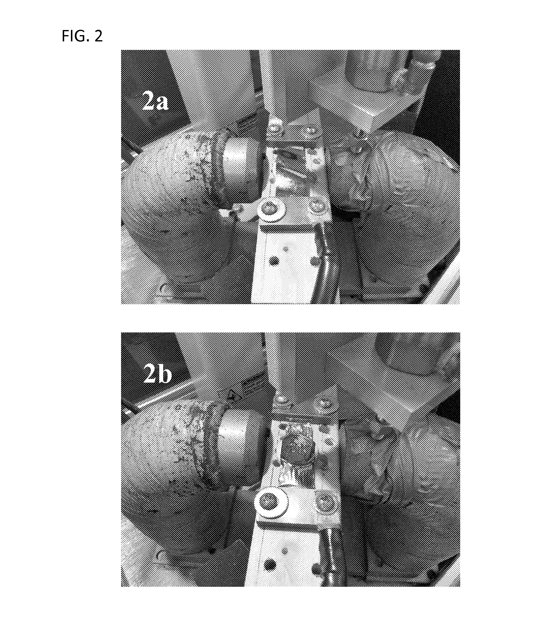
[0068]As a demonstration of the method in a simple molding case, a thin sheet of metallic glass (Metglas MBF 50—Ni-based brazing alloy) produced by planar flow casting is used. The sheet is in the form of a ribbon of width 1-2″, thickness of about 30-40 μm. Such ribbons are commercially available in long lengths from the Metglas Division of Hitachi Metals. A 0.262 Farad capacitor band controlled by a silicon rectifier was used. A simple demonstration die tool was fabricated from a machinable ceramic, Macor. For demonstration, a Macor die of circular symmetry with concentric grooves machined in the surface was chosen as shown in FIGS. 2A to D.

[0069]A reasonably homogeneous magnetic field of ˜1 kG was applied in the region surrounding the mold and was provided by a permanent magnet as seen in FIGS. 2A and 2B. The capacitor was charged to voltages in the range of 20-40 volts and discharged through copper leads and a copper clamping strip on the ribbon. FIG. 2A shows the original...

example 2

Sheet Forming

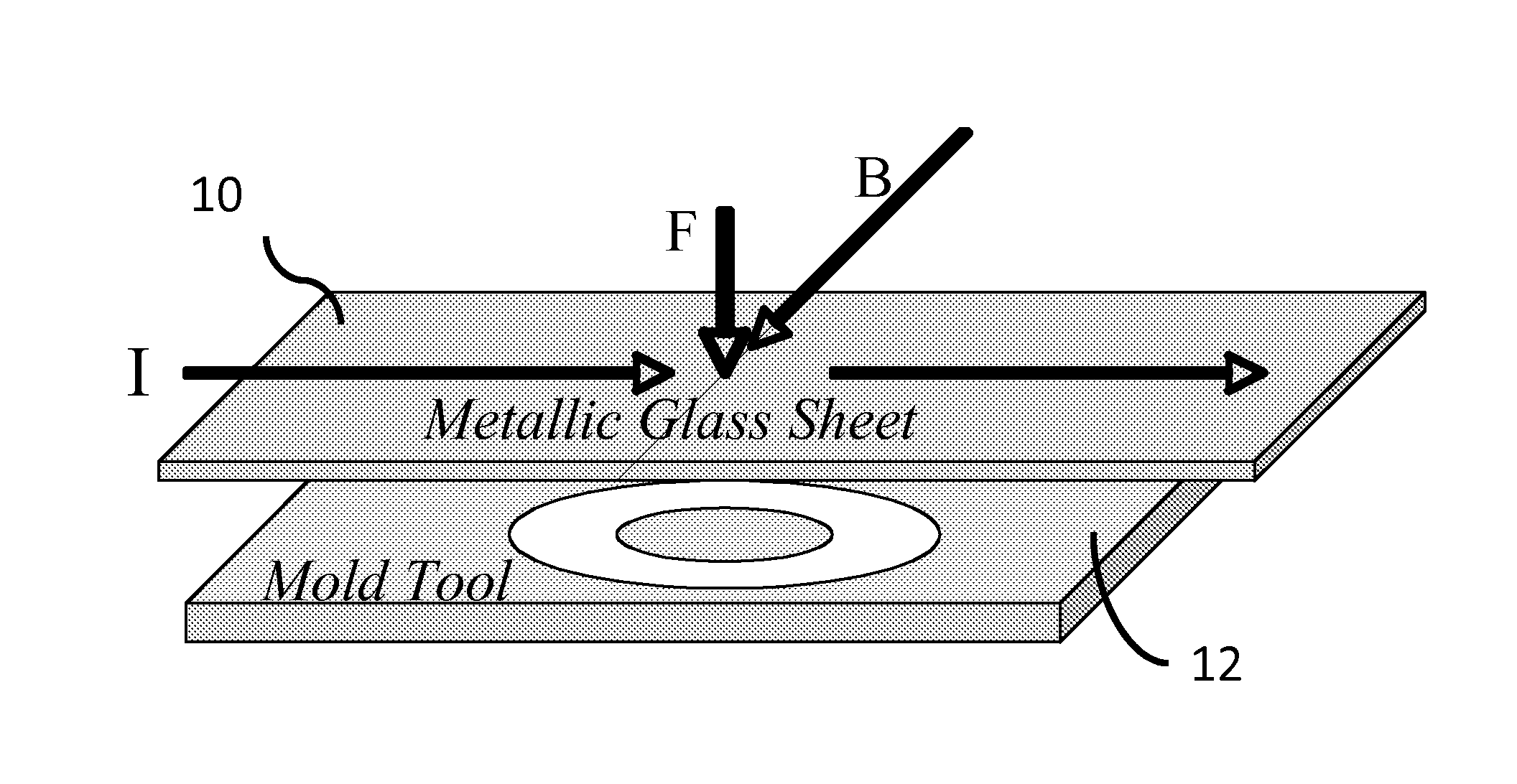
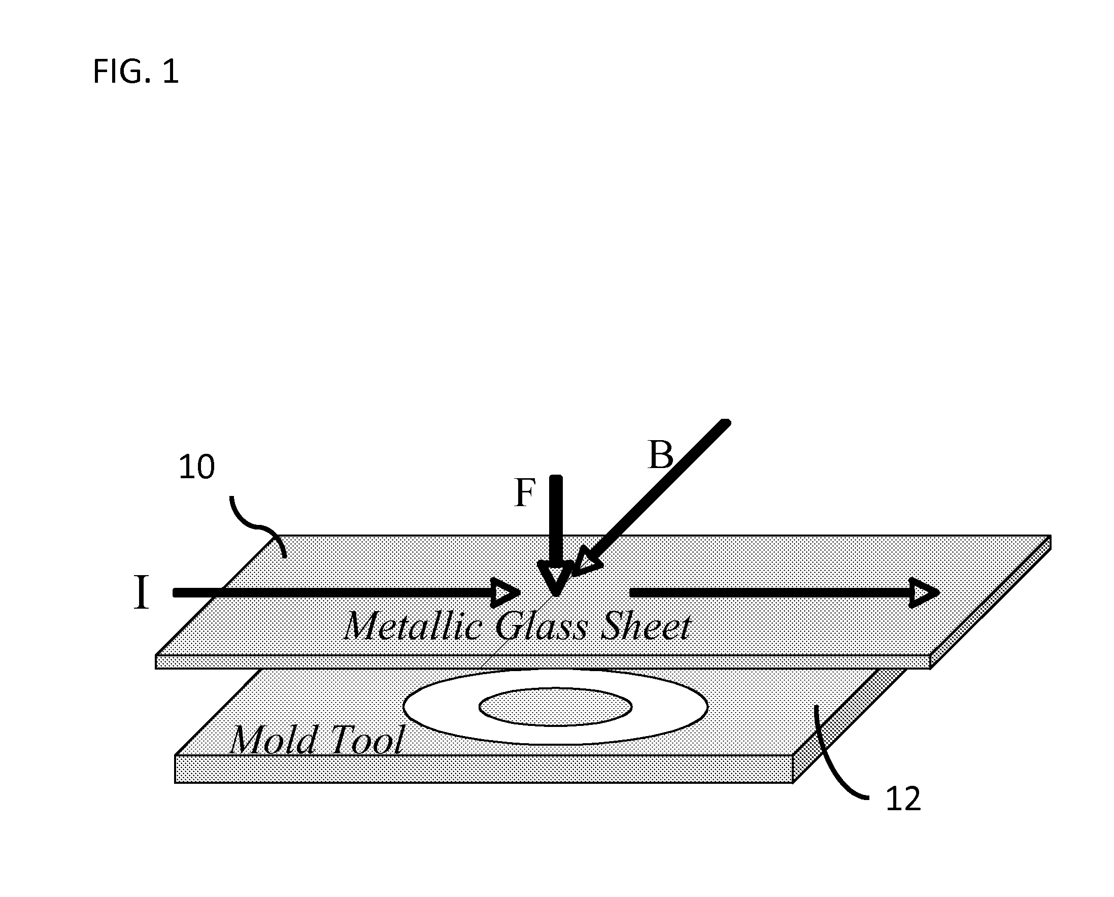
[0071]FIG. 3 shows an exemplary set-up for a method of forming sheets from a plate using twin rolls. As shown, in this embodiment an electromagnetic force (F) is exerted on a square or rectangular bar (14) of metallic glass located above the gap between two rotating rollers (16). The electrical discharge (I) is transferred to the sample by electrodes (not shown), which contact the ends of the bar (14). Current is induced along the length of the bar. A static magnetic field (B) is applied normal to the bar (14) and parallel to the plane defined by the two axes (18) of the twin rollers (16). The electromagnetic force drives the heated bar into the gap between the rollers to produce a rolled sheet. The bar may be contained in a vertical channel (not shown) made of electrically non-conducting material in order to confine and efficiently guide the material through the rollers.

example 3

Injection Molding & Extrusion of a Net-Shaped Component

[0072]In another embodiment, the basic method may be used to injection mold a square rod into a mold cavity of net-shape. As shown in FIG. 4, in this embodiment an electromagnetic force (F) can be used to create a pressure gradient along the length of a metallic glass sample (20) during discharge heating of the rod by a current (I) across its width provided by two bar shaped electrodes (22). To prevent leakage, the charge is confined by non-conducting containment walls (24). A mold tool with suitable gating and mold cavity can be provided (not shown) that would then be filled by the injected liquid as it is heated to a suitable process temperature (as described above).

[0073]Alternatively, the same set-up can be used for a method of extrusion of a net-shaped component of uniform cross-section using an extrusion die. In this embodiment, the apparatus is used to force a heated charge of metallic glass through an extrusion die. In t...


PUM

PropertyMeasurementUnit
viscosityaaaaaaaaaa
discharge time constantaaaaaaaaaa

Abstract

An apparatus and method of uniformly heating, rheologically softening, and thermoplastically forming metallic glasses rapidly into a net shape using a rapid capacitor discharge forming (RCDF) tool in combination with an electromagnetic force generated by the interaction of the applied current with a transverse magnetic field. The RCDF method utilizes the discharge of electrical energy stored in a capacitor to uniformly and rapidly heat a sample or charge of metallic glass alloy to a predetermined “process temperature” between the glass transition temperature of the amorphous metal and the equilibrium melting point of the alloy in a time scale of several milliseconds or less, at which point the interaction between the electric field and the magnetic field generates a force capable of shaping the heated sample into a high quality amorphous bulk article via any number of techniques including, for example, injection molding, dynamic forging, stamp forging, and blow molding in a time scale of less than one second.

Description

CROSS-REFERENCE TO RELATED APPLICATIONS[0001]The current application claims priority to U.S. Provisional Application No. 61 / 322,209, filed Apr. 8, 2010, the disclosure of which is incorporated herein by reference.FIELD OF THE INVENTION[0002]This invention relates generally to a novel method of forming metallic glass; and more particularly to a process for forming metallic glass using rapid capacitor discharge heating and a magnetic field to apply an electromagnetic forming force.BACKGROUND OF THE INVENTION[0003]Amorphous materials are a new class of engineering material, which have a unique combination of high strength, elasticity, corrosion resistance and processability from the molten state. Amorphous materials differ from conventional crystalline alloys in that their atomic structure lacks the typical long-range ordered patterns of the atomic structure of conventional crystalline alloys. Amorphous materials are generally processed and formed by cooling a molten alloy from above t...

Claims


Application Information

Patent Timeline
Patent Type & Authority Applications(United States)
IPC IPC(8): B21J5/04
CPCB21D26/14B23K35/3033C21D1/04C21D10/00B21J5/04C22C1/002C22C45/00C22F3/02C21D2201/03C22C1/11C22F1/00C21D1/38
Inventor JOHNSON, WILLIAM L.KALTENBOECK, GEORGDEMETRIOU, MARIOS D.ROBERTS, SCOTTSAMWER, KONRAD
Owner CALIFORNIA INST OF TECH
Why Eureka
Try Eureka