Durable Anti-reflection coatings

a coating and anti-reflection technology, applied in coatings, instruments, optics, etc., can solve the problems of reducing the reflectivity, destroying the interference of reflected light, and reducing the reflectivity significantly over the visible wavelength range of 400 to 700 nanometers (nm), so as to reduce the reflectivity of light and excellent durability

Inactive Publication Date: 2012-01-26
YAZAKI CORP
View PDF1 Cites 42 Cited by
  • Summary
  • Abstract
  • Description
  • Claims
  • Application Information

AI Technical Summary

Benefits of technology

[0013]The substrate of the present invention may be any of various materials, shapes, and sizes. In preferred embodiments, the substrate is a transparent polymer or glass, in the shape of a flat or curved panel having two main surfaces, such as an ophthalmic lens. The article of the present invention exhibits r

Problems solved by technology

These coatings, while effective at reducing reflectivity, do not provide satisfactory durability for particularly harsh mechanical stress such as scratching or abrading, exposure to harsh chemicals such as acids or bases, and environmental conditions of temperature, humidity, sunshine or UV light exposure.
Other anti-reflection coatings comprise a multi-layer stack having carefully controlled, alternating high and low relative refractive indexes, which when combined with prescribed thicknesses of each layer, results in destructive interference of reflected light and significantly greater reduction in reflectivity over the visible wavelength range of 400 to 700 nanometers (nm).
This matte finish is unacceptable for certain applications such as ophthalmic lenses.
While various single-layer and multi-layer anti-reflection coatings have been generally ef

Method used


Image

  • Durable Anti-reflection coatings
  • Durable Anti-reflection coatings
  • Durable Anti-reflection coatings

Examples


example 1

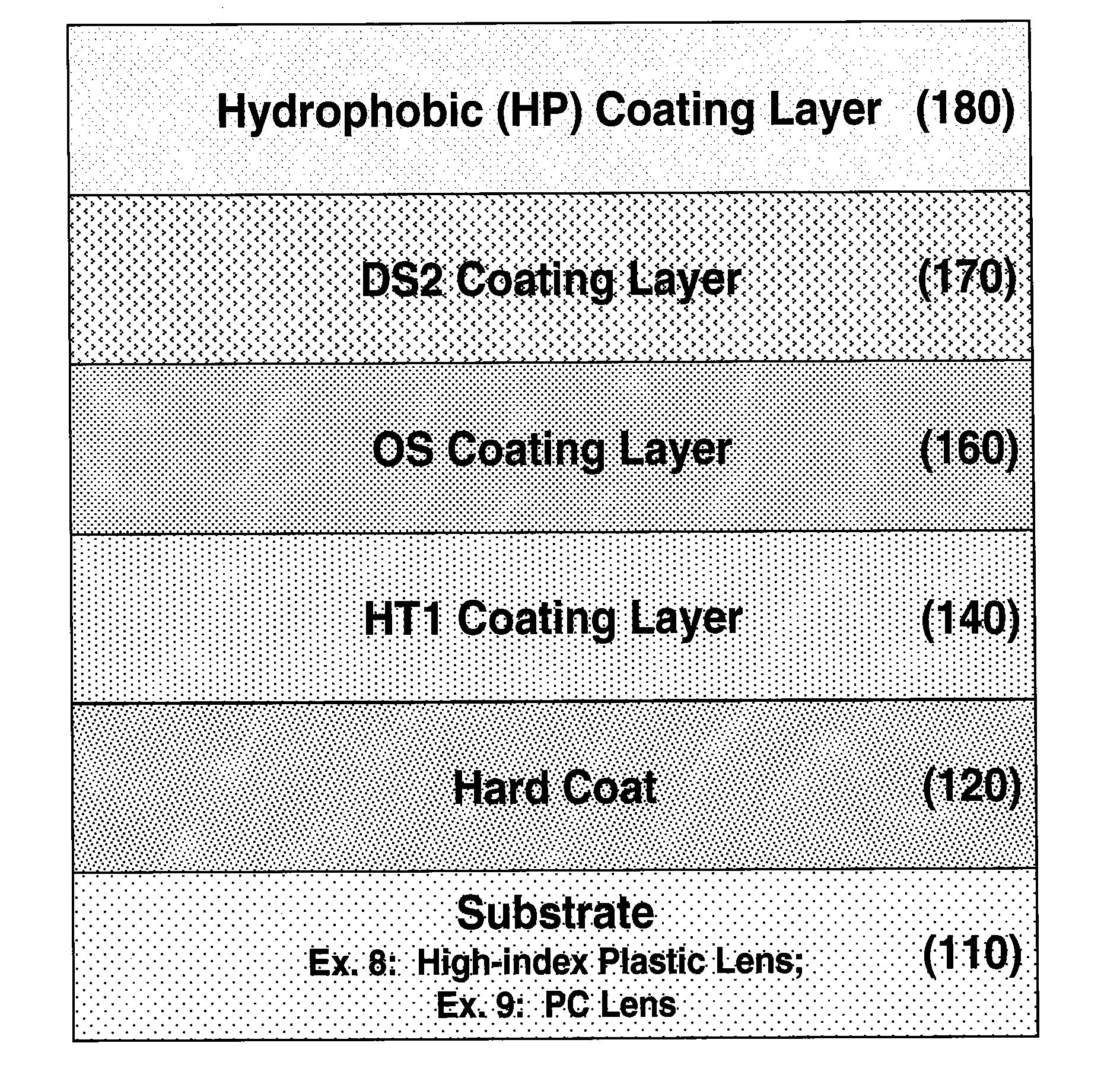
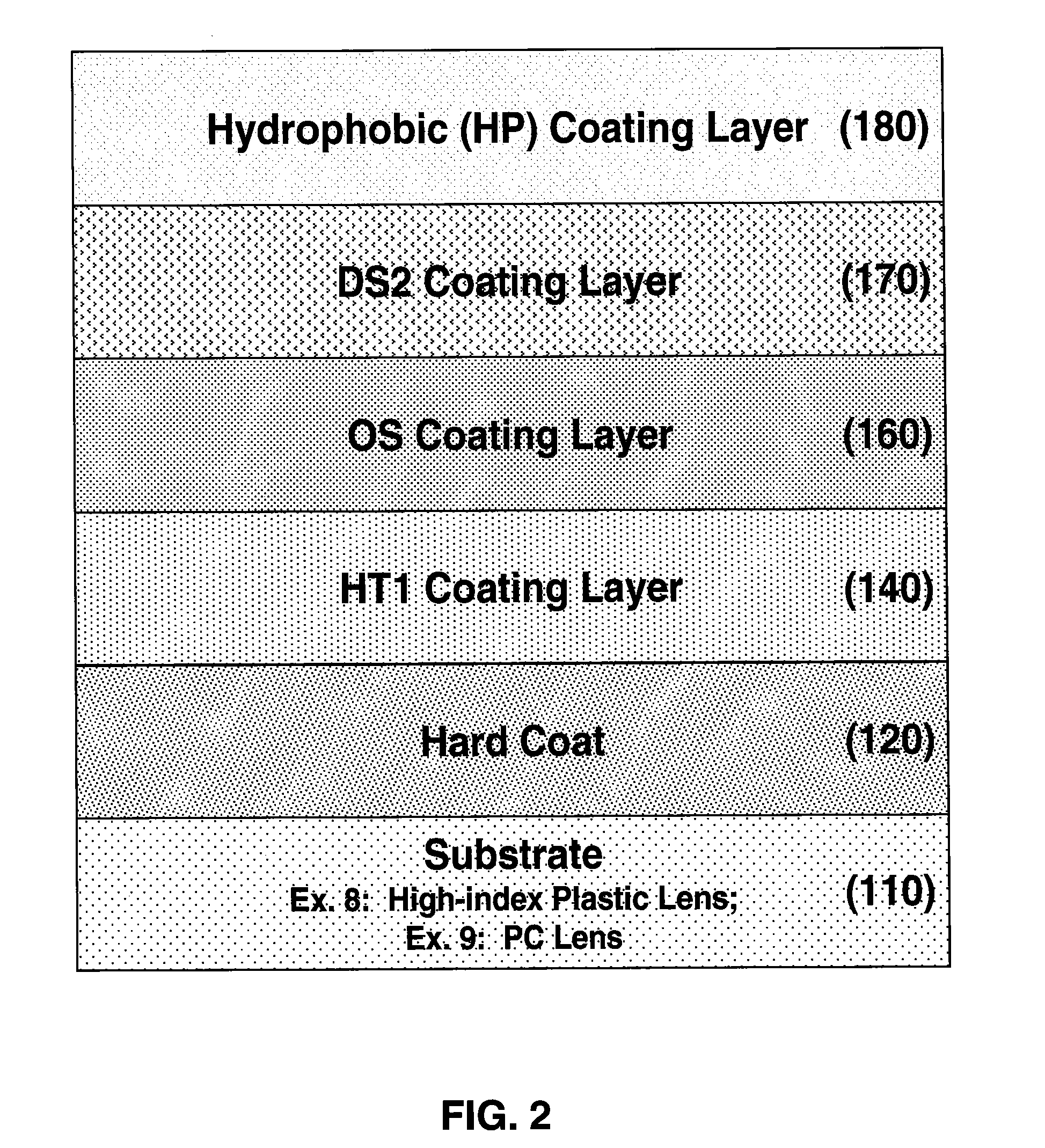
Preparation of an Epoxide-Silica Coating Composition (OS)

[0095]A low refractive index, epoxide-silica coating composition, designated as the “OS” composition, was prepared as follows:

[0096]In a closed plastic container, about 368.2 grams of reagent-grade ethanol (Fisher Chemical Co., catalog No. A995-4), about 77.5 grams of deionized water, about 8.6 grams of nitric acid (about 70 wt % HNO3) (Fisher Chemical Co., catalog No. A200-500) and about 1.0 grams of sodium acetate (Sigma Aldrich, catalog No. 470899) were mixed using a magnetic stirring plate, for about 30 minutes at about 350 rpm and at 65° C., to form a first mixture. Then, about 81.8 grams of tetramethyl orthosilicate (a non-epoxy-functional silicon alkoxide, Sigma Aldrich, catalog No. 218472) were added to the first mixture, to form a second mixture. The second mixture was stirred for about 2 hours, at about 350 rpm and at 65° C. Then, about 497.3 grams of reagent-grade ethanol and 865.5 grams of 1-methoxy-2-propanol (Sig...

example 2

Preparation of a Low Refractive Index Silica Coating Composition (DS2)

[0099]This low-refractive index silica coating composition, designated as the “DS2” composition, was prepared as follows:

[0100]In a closed plastic container, about 199.7 grams of reagent-grade ethanol, about 46.0 grams of deionized water, about 5.1 grams of nitric acid (70 wt %), and about 0.6 grams of sodium acetate were mixed for about 30 minutes, at about 350 rpm and at 65° C., to form a first mixture. Then, about 48.6 grams of tetramethyl orthosilicate (a silicon alkoxide) were added to the first mixture, to form a second mixture. The second mixture was stirred for about 2 hours, at about 350 rpm and at 65° C. Then, about 684.9 grams of reagent-grade ethanol and 1015.1 grams of 1-methoxy-2-propanol were added to the second mixture, to form a third mixture. After stirring the third mixture for about 15 hours at about 350 rpm and at ambient temperature, it was filtered through a 0.2-μm filter, to form the DS2 co...

example 3

Preparation of a High Refractive Index Titania Coating Composition (HT1)

[0101]The preparation of this high-refractive index coating composition, designated as the “HT1” composition, was described in detail in US Patent Application US 2008 / 0003373 A1 to Yan et al, the contents of which are incorporated by reference.

[0102]In a closed plastic container, about 317.1 grams of reagent-grade ethanol, about 5.9 grams of hydrochloric acid (about 36 wt % HCl) (Fisher Chemical, catalog No. A508-500), and about 5.7 grams of deionized water were mixed for about 5 minutes using a magnetic stirrer, at about 200 rpm and at ambient temperature, to form a first mixture. Then, about 106.4 grams of titanium(IV) isopropoxide (Sigma Aldrich, catalog No. 205273) were added to the first mixture, to form a second mixture, and this second mixture was stirred for about 60 minutes, at about 200 rpm and at ambient temperature. Then, about 1552.5 grams of reagent-grade ethanol, about 2.1 grams of hydrochloric ac...


PUM

PropertyMeasurementUnit
Thicknessaaaaaaaaaa
Nanoscale particle sizeaaaaaaaaaa
Mechanical propertiesaaaaaaaaaa

Abstract

An article comprising a substrate and an anti-reflection coating, and methods for depositing the coating, are disclosed. The coating comprises (a) a first coating layer having a high refractive index deposited on the substrate; (b) an epoxide-silica coating layer deposited onto the high refractive index coating layer, comprising an inorganic silica component and an organic organo-silicate component, and (c) a silica coating layer consisting essentially of silica, deposited directly onto the epoxide-silica coating layer. The anti-reflection coating optionally comprises a stack of coating layers, between the first high refractive index coating layer and the epoxide-silica coating layer, having alternating a low refractive index and a high refractive index. Individual coating layer compositions, refractive indexes, and thicknesses are carefully controlled such that reflectance is minimized through destructive interference in the visible light wavelength range of 400 to 700 nm. The resulting deposited coating provides excellent mechanical, chemical, and environmental durability.

Description

[0001]This application is a continuation of PCT / US2010 / 052080, filed Oct. 8, 2010; which claims the priority of U.S. Provisional Application Nos. 61 / 250,206, filed Oct. 9, 2009. The contents of the above-identified applications are incorporated herein by reference in their entirety.TECHNICAL FIELD[0002]This invention relates generally to articles comprising a substrate and an anti-reflection coating deposited onto the substrate, and a process for depositing the anti-reflection coating onto the substrate. More particularly, this invention relates to an anti-reflection coating having improved mechanical, chemical, and environmental durability, and a process for depositing this coating onto transparent substrates such as polymeric or glass panels and ophthalmic lenses.BACKGROUND OF THE INVENTION[0003]Antireflection (AR) coatings on transparent articles reduce the reflectance of visible light from the articles and enhance the transmission of such light into, or through, the articles. Wh...

Claims


Application Information

Patent Timeline
IPC IPC(8): G02B1/11B05D5/06C08J7/043C08J7/046
CPCB32B33/00B32B2307/40B32B2307/418G02B1/111C03C2217/73C03C2217/76C08J7/045C03C17/42C08J7/0423C08J7/043C08J7/046
Inventor YAN, YONGANKAYGEE, ANANDRAYCHAUDHURI, SATYABRATA
Owner YAZAKI CORP
Why Eureka
Try Eureka