Focusing multimodal optical microprobe devices

a multi-modal, optical microprobe technology, applied in the field of optical microprobe devices, can solve the problems of high resolution of existing near-field optical microprobes, difficult task of developing compact light-focusing tools for photonics and biomedical applications, and low optical throughput, so as to achieve efficient coupling of radiation sources, high spatial resolution, and high optical throughput

Active Publication Date: 2012-04-19
JUNIVERSITI OF NORT KAROLINA EHT SHARLOTT
View PDF4 Cites 9 Cited by
  • Summary
  • Abstract
  • Description
  • Claims
  • Application Information

AI Technical Summary

Benefits of technology

[0007]In various exemplary embodiments, the present invention provides optical microprobe devices and methods that utilize a plurality of transparent or semitransparent small scale spheres, cylinders, or the like of the same or varying size and the same or varying index of refraction to focus a beam of light and create a usable photonic nanonjet, thereby providing reasonably high spatial resolution (i.e. on the order of or smaller than λ) and high optical throughput. In the simplest case, the small scale spheres or cylinders are axially chained together in a contact configuration within a hollow waveguide, a hollow-core photonic crystal fiber, in a capillary tube, integrated with an optical fiber, or assembled on a chip or other substrate (patterned or non-patterned), with the last small scale sphere or cylinder adjacent and / or exposed to an external medium. This periodically focuses coupled light along the chain, giving rise to periodic optical modes referred to as photonic “nanojet induced modes” (NIMs). If desired, focused beams with progressively smaller dimensions may be obtained along the chain. The last photonic nanojet is operable for acting on a specimen. Non-axial and non-contact configurations (both regular and irregular) are also contemplated. These optical microprobe devices and methods find applicability in material and biomedical modification and cutting applications (possibly in combination with conventional or novel micromanipulation techniques), such as laser-tissue surgery, material analysis applications, data storage applications, and the like. Advantageously, the optical microprobes of the present invention may utilize radiation sources with narrow spectral lines (i.e. lasers) or broad emission spectra, operate over a wide range of wavelengths and frequencies, may be used in multimodal systems with “imperfect” radiation sources, and provide the efficient coupling of radiation source to focusing element, with relatively small losses in the transmission of optical power. Further, the optical microprobes of the present invention are designed to operate over very short working distances and are not unacceptably affected by specimen contact. Still further, the optical microprobes of the present invention may be used in conjunction with robust and flexible multimodal optical fiber or hollow waveguides. In addition, the optical microprobes of the present invention may operate as sealed devices, making them more impervious to environmental intrusion. Finally, the microspheres or microcylinders in the microprobes of the present invention may be made of optically nonlinear or optically active materials. This allows using the above-described light-focusing effects in combination with such effects as nonlinear frequency generation, optical amplification, and lasing. In these applications, the periodicity of the chain provides a quazi-phase-matching condition for nonlinear frequency generation or optical feedback for lasing. Due to the high concentration of light in the photonic nanojet regions inside the spheres or cylinders, such structures have increased nonlinear response and reduced lasing threshold combined with tight focusing of the output beams, a highly desirable combination of properties in many optoelectonic applications.

Problems solved by technology

The task of development of compact light-focusing tools for photonics and biomedical applications is challenging due to the multimodal structure of the beams propagating in the often flexible delivery systems of such devices.
Conventional optical microprobe devices and methods suffer from a number of significant shortcomings.
Existing near-field optical microprobes have high resolution, but extremely limited optical transmission.
However, these optical microprobes typically fail to deliver adequate optical power.
Existing far-field optical microprobes have high optical transmission properties, but very limited spatial resolution, especially in the case of multimodal input beams.
However, such perfectly conical beams of light are not readily available in conventional optical delivery systems used in laser-tissue surgery and other applications.
It should be noted, however, that single mode optical fibers are not readily available in the mid-infrared range of the spectrum.
They also have limited coupling efficiency with many practical radiation sources, and limited power transmission properties.
Instead, using multimodal beams in such systems results in greatly diminished spatial resolution, well below the diffraction limit.
In any event, such optical microprobes, and others, do not allow for direct contact with a sample, i.e. tissue contact in a biomedical application, due to high refractive indices (˜1.33 or larger) of the later, leading to defocusing of the beam.
These optical microprobes also typically fail to deliver adequate optical power.
Further existing optical microprobes utilize exotic metamaterials with a negative index of refraction, permittivity, and permeability and are extremely challenging to fabricate.
In addition, these exotic metamaterials have a limited usable frequency range.
In addition, such optical microprobes require the use of single mode fibers (SMFs) or inflexible waveguides, not readily available in or suitable for many applications.
Finally, in all of the above cases, it is difficult to control the separation between the tip of the microprobe and the sample, also referred to as the “working distance,” with the accuracy required.
More importantly, if the focusing of light is required in a contact mode, it is practically impossible to achieve wavelength-scale focused spot sizes in sample / tissue for microprobes operating in a far field due to the high refractive index of the sample / tissue.

Method used


Image

  • Focusing multimodal optical microprobe devices
  • Focusing multimodal optical microprobe devices
  • Focusing multimodal optical microprobe devices

Examples


Embodiment Construction

[0023]In accordance with the devices and methods of the present invention, the teem “optical microprobe” is defined as an instrument that is capable of selectively applying a stable and focused beam of light or other radiation to a small scale portion of a sample in a directed manner for modification, analytical, or other purposes. It is variously also referred to herein as a “focusing multimodal microprobe.” These and all similar terms should be considered to be synonomous.

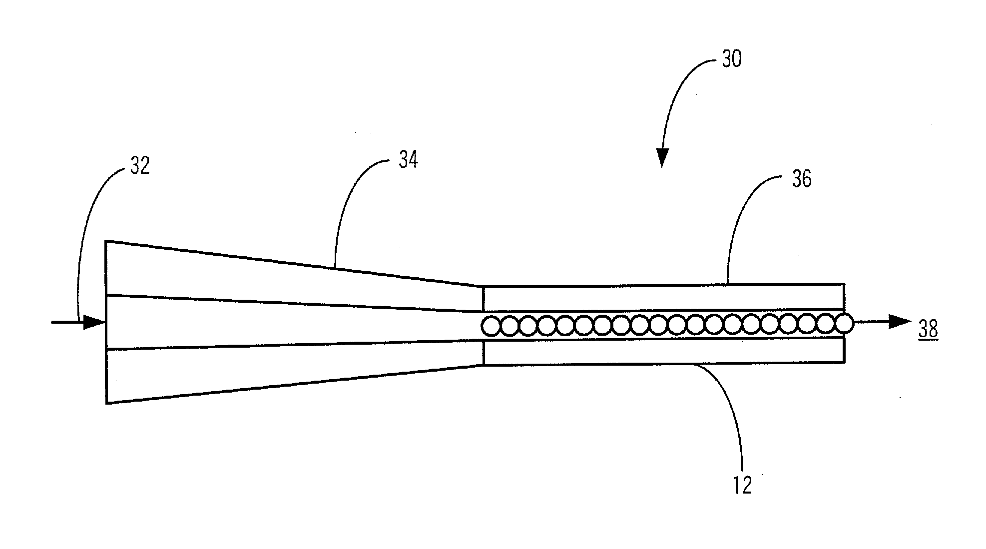
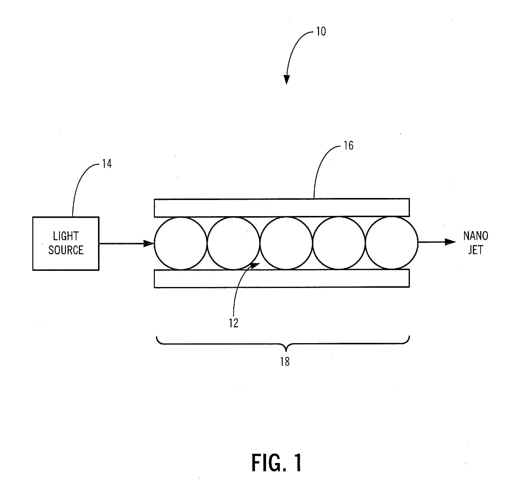
[0024]Referring to FIG. 1, in one exemplary embodiment of the optical microprobe 10 of the present invention, a plurality of transparent or semitransparent small scale spheres, cylinders, or the like 12 of the same or varying size and the same or varying index of refraction are used to focus a beam of light or other radiation selectively emitted by an optically coupled radiation source 14. Preferably, these spheres or cylinders 12 each have a diameter of between about one wavelength of light and several thousand ...


PUM


Abstract

The present invention provides an optical microprobe device and method for focusing multimodal radiation with wavelength-scale spatial resolution and delivering the focused radiation to a specimen, including: a radiation source; and one or more of a plurality of optically transparent or semitransparent spheres and a plurality of optically transparent or semitransparent cylinders optically coupled to the radiation source; wherein the one or more of the plurality of optically transparent or semitransparent spheres and the plurality of optically transparent or semitransparent cylinders periodically focus radiation optically transmitted from the radiation source such that radiation ultimately transmitted to the specimen has predetermined characteristics. Preferably, the spheres or cylinders are assembled inside one of a hollow waveguide, a hollow-core photonic crystal fiber, a capillary tube, and integrated in a multimode fiber. Alternatively, the spheres or cylinders are assembled on a substrate. Optionally, the optical microprobe device also includes one or more of a waveguide, an optical fiber, a lens, and an optical structure disposed between the radiation source and the spheres or cylinders. Optionally, the spheres or cylinders are made from optically nonlinear or active materials that permit efficient nonlinear frequency generation and low-threshold lasing using the optical microprobe device.

Description

CROSS-REFERENCE TO RELATED APPLICATION[0001]The present non-provisional patent application / patent claims the benefit of priority of U.S. Provisional Patent Application No. 61 / 187,690, filed on Jun. 17, 2009, and entitled “OPTICAL MICROPROBE WITH SUBWAVELENGTH RESOLUTION,” the contents of which are incorporated in full by reference herein.STATEMENT REGARDING FEDERALLY SPONSORED RESEARCH OR DEVELOPMENT[0002]The U.S. Government has a paid up license in the present invention and the right, in limited circumstances, to require the patent application / patent owner to license to others on reasonable terms as provided for by the terms of Award No. ARO W911NF-09-1-0450 awarded by the Army Research Office and Award No. ECCS-0824067 awarded by the National Science Foundation.FIELD OF THE INVENTION[0003]The present invention relates generally to optical microprobe devices and methods with wavelength-scale spatial resolution that are capable of using multimodal optical delivery systems, such as h...

Claims


Application Information

Patent Timeline
Patent Type & Authority Applications(United States)
IPC IPC(8): B01J19/12
CPCA61B18/201A61B2018/2065A61B2018/2227A61B2018/2266B82Y15/00B82Y20/00G02B6/4206G02B6/02304G02B6/02328G02B6/032G02B6/12004G02B6/32G02B6/0096
Inventor ASTRATOV, VASILY N.
Owner JUNIVERSITI OF NORT KAROLINA EHT SHARLOTT
Why Eureka
Try Eureka