Tools and Methods for Forming Semi-Transparent Patterning Masks

a mask and semi-transparent technology, applied in the field of semi-transparent patterning masks, can solve the problems of widened mask openings, significant unwanted etching of critical mask features, and inferior electrical conductivity of traces made by “printed electronic” techniques, and achieves the effects of high resolution patterning, rapid and low-cost tool fabrication, and the ability to form tools

Active Publication Date: 2012-05-24
MICROCONTINUUM
View PDF4 Cites 21 Cited by
  • Summary
  • Abstract
  • Description
  • Claims
  • Application Information

AI Technical Summary

Benefits of technology

[0010]The subject technology addresses the previously-noted limitations, and can provide improved methods for forming semi-transparent (‘S-T’) imprint tools (templates or molds) for use in producing residue-free patterning masks and application of such method to produce large-area semi-transparent films. The improvements inherent to the subject technology, as described in detail below, can include higher resolution patterning, rapid and low-cost tool fabrication, the ability to form tools that are rigid or flexible, alteration of the as

Problems solved by technology

The electrical conductivity of traces made by “printed electronic” techniques, typically using metal particle or metal precursor type inks, are generally inferior to those made from bulk metals and often require thermal post-processing to achieve acceptable electrical conductivity.
One limitation, however, of the NIL process for forming etch masks is that a very thin layer of residual polymeric material (known as the ‘residue’ or ‘scum’ layer) is left in the bottoms of the mask (i.e., closest to the substrate on which the mask is formed) after imprinting, and this layer must be removed prior to further processing (deposition or removal).
Incomplete removal of the residual material from the mask will result in defects after subsequent steps: e.g., patches of missing metal after metallization in additive processing and stray patches of metal after etching in subtractive processing.
Although ideally this is an anisotropic process, where material perpendicular to the source direction is removed at a faster rate than that in the parallel direction, this is not always the case, resulting in potentially significant unwanted etching of critical mask features, for example that results in widened mask openings that produces incorrect line widths.
In addition, the residue removal process has other drawbacks: 1) it requires expensive vacuum equipment with specialized gas handling and controls, 2) pump-down time to reach operation pressure adds to the processing time, 3) the etch process itself can be slow, also adding to the process time, 4) non-uniformities in the plasma field can cause non-uniform polymer removal and result in areas that are under-etched (areas of residue left intact) or over-etched (areas of mask polymer removed), and/or 5) the etch process can be detrimental to other elements of the structure (including by unwanted material removal, chemical interactions, re-deposition of etch by-products, hardening of the mask, etc.).
How

Method used


Image

  • Tools and Methods for Forming Semi-Transparent Patterning Masks
  • Tools and Methods for Forming Semi-Transparent Patterning Masks
  • Tools and Methods for Forming Semi-Transparent Patterning Masks

Examples


Embodiment Construction

[0036]In the following detailed description, numerous specific details are set forth by way of examples in order to provide a thorough understanding of the relevant teachings. However, it should be apparent to those skilled in the art that the present teachings may be practiced without such details. In other instances, well known methods, procedures, and / or techniques have been described at a relatively high-level, without detail, in order to avoid unnecessarily obscuring aspects of the present teachings.

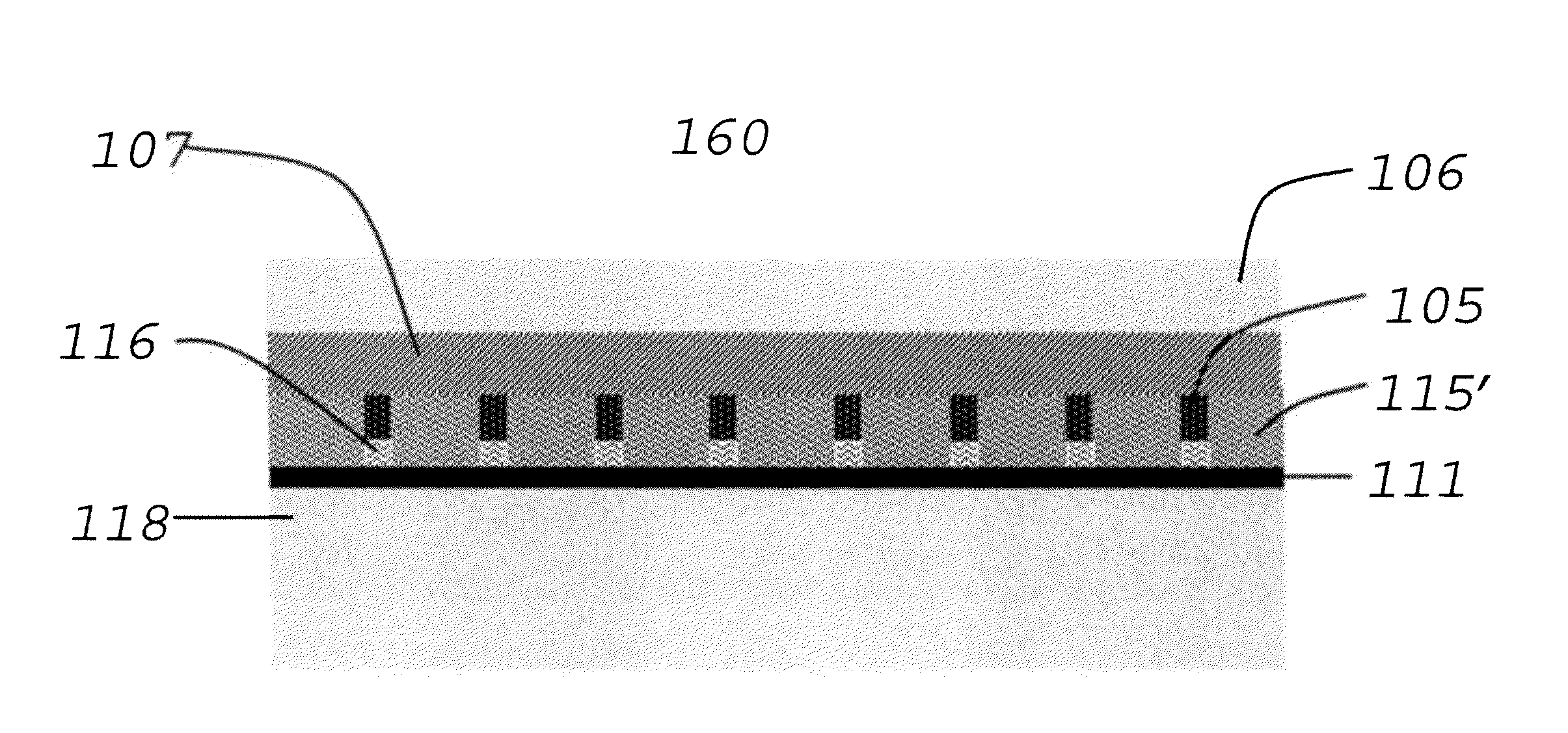
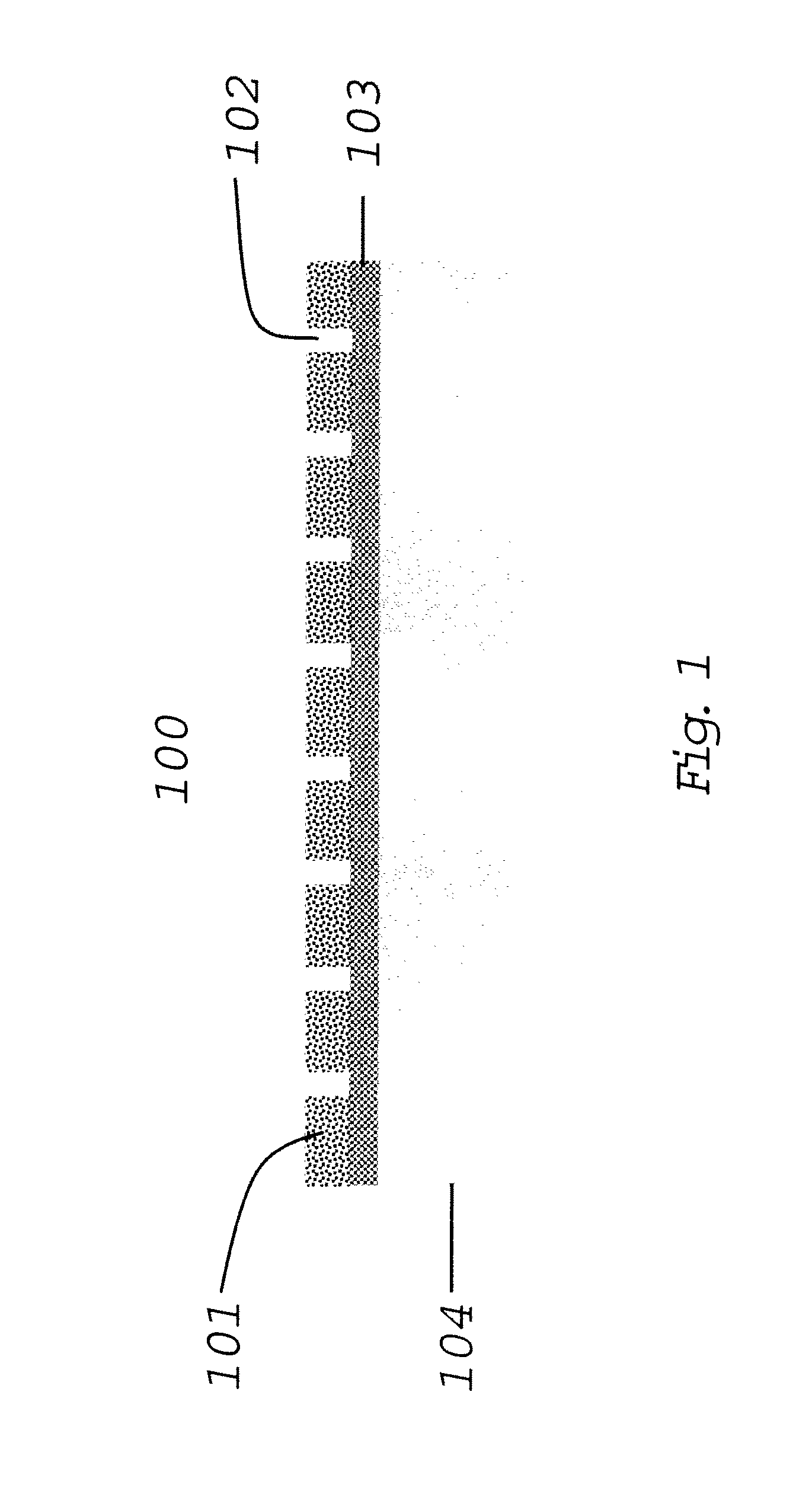
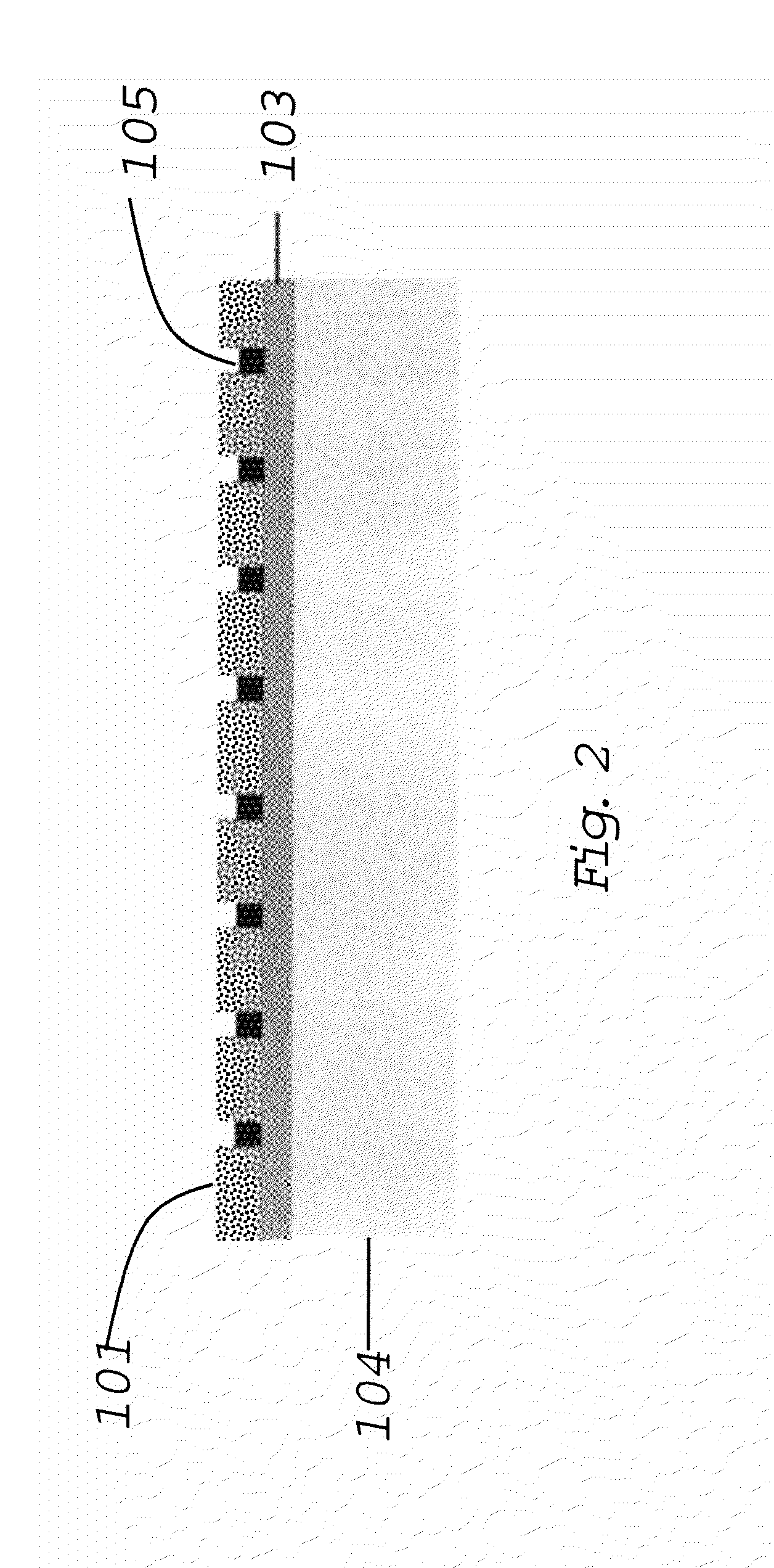
[0037]The subject technology is directed toward improved methods and systems for forming rigid and flexible semi-transparent (S-T) imprint tools. A significant advantage of such tools is that they can be used to make imprint lithography masks that do not require plasma etching to remove the residue (scum) material that is an unwanted characteristic of the formation of such masks. Such plasma-etch-free masks, when used with the methods of additive and / or subtractive pattern formation...


PUM

PropertyMeasurementUnit
Fractionaaaaaaaaaa
Lengthaaaaaaaaaa
Lengthaaaaaaaaaa

Abstract

Means, apparatus, systems, and/or methods are described for forming improved rigid or flexible semi-transparent imprinting templates. These templates can be used to produce patterning masks having improved resolution that do not require plasma etching for residue removal. The methods and apparatus are compatible with roll-to-roll manufacturing processes and enable roll-to-roll formation of a wide range of metal patterned films.

Description

RELATED APPLICATIONS[0001]This application claims priority to U.S. Provisional Patent Application No. 61 / 416,011, filed 22 Nov. 2010, and entitled “Tools and Methods for Forming Patterning Masks,” the entire content of which is incorporated by reference herein. This application is related to the following applications, each of which is incorporated herein by reference in its entirety: U.S. application Ser. No. 11 / 337,013 filed 20 Jan. 2006 and entitled “Replication Tools And Related Fabrication Methods and Apparatus”; U.S. application Ser. No. 11 / 471,223 filed 26 Jun. 2006 and entitled “Systems and Methods for Roll-to-Roll Patterning”; U.S. application Ser. No. 11 / 711,928 filed 27 Feb. 2007 and entitled “Formation of Pattern Replicating Tools”; U.S. application Ser. No. 11 / 830,718 filed 30 Jul. 2007 and entitled “Addressable Flexible Patterns”; and, U.S. application Ser. No. 12 / 270,650 filed 13 Nov. 2008 and entitled “Methods and Systems for Forming Flexible Multilayer Structures”.B...

Claims


Application Information

Patent Timeline
IPC IPC(8): B28B11/08H01B13/00B28B7/36
CPCH01L51/0023H10K71/621B29C59/002B29C59/022B29C2059/023B29K2905/00B29K2995/0026
Inventor SLAFER, W. DENNIS
Owner MICROCONTINUUM
Why Eureka
Try Eureka