Anisotropic conductive polymer material

a polymer material and anisotropic technology, applied in the direction of oxide conductors, conductors, non-metal conductors, etc., can solve the problems of difficult dispersion of nanotubes, difficult industrial production of carbon nanotubes, and limited life of mixed systems

Active Publication Date: 2012-06-14
CONDALIGN AS
View PDF7 Cites 52 Cited by
  • Summary
  • Abstract
  • Description
  • Claims
  • Application Information

AI Technical Summary

Benefits of technology

[0092]The adhesive can be ultraviolet light (UV) curing adhesives, also known as light curing materials (LCM). UV curing adhesives have rapid curing time and strong bond strength. They can cure in as short times as a second and many formulations can bond dissimilar materials and withstand harsh temperatures. These qualities make UV curing adhesives essential to the manufacturing of items in many industrial markets such as electronics, telecommunications, medical, aerospace, glass, and optical. Unlike traditional adhesives, UV light curing adhesives not only bond materials together but they can also be used to seal and coat products.
[0143]It is a further object to provide the aforesaid method and adhesive composition with inexpensive means for industrial scale applications.

Problems solved by technology

Mixed systems have limited lifetime and must be re-mixed prior to use.
A disadvantage with the method is that carbon nanotubes are very expensive and difficult to produce on an industrial scale.
A dispersion of nanotubes is difficult to store and require specific manufacturing steps like homogination or sonication prior to application of the dispersion to the substrate and electrode.
These changes are frequently undesirable, e.g. a decrease in material strength and transparency and change in colour.
Mixed systems have limited lifetime and must be re-mixed prior to use.
A common problem is that a film or layer even when manufactured to a uniform thickness, will have non-uniform conductivity because the filler material will not distribute evenly.
The problem is well-known in polymer physics and stems from the mutual incompatibilities of filler materials and polymer matrix, which means that only small amount of fillers can be mixed with the matrix to lead to the stable mixture.
Moreover, the mixing process applied for higher filler quantities must be so vigorous that the filler particles may get broken.
A disadvantage with prior art is that carbon nanotubes are very expensive and difficult to produce on an industrial scale.
A dispersion of nanotubes is difficult to store and require specific manufacturing steps like homogenation or sonication prior to application of the dispersion to the substrate.
The process of making holes in the polymer matrix to be filled by conductive materials as described in U.S. Pat. No. 4,101,689A is also complicated.
Firstly, soldering requires heavy metals such as lead which are toxic and require expensive measures when the cells are disposed.
However, thinner layers suffer from cracks arising from soldering.
Thirdly, soldering may cause oxidation of connected materials.
This can have detrimental effects to the solar cells as excess stress will promote breakage and warping of the surface.
This becomes increasingly problematic when solar cells are produced thinner to reduce material usage and costs.
This constitutes a problem because high amounts of conductive particles weakens mechanical properties of the adhesive and increases material cost.
For diverse spherical or largely 3-dimensional particles, this threshold is theoretically between 1-17 vol %, but in practice the lower limit is usually not sufficient for securing conductivity.
A disadvantage of such CNTs is, however, that they are difficult to produce on an industrial scale.
The carbon nanotubes are difficult to produce on an industrial scale and are expensive and applications involving larger volumes are not realistic today.
CNTs are, moreover, difficult to mix with polymers to form high quality dispersions.
It is however difficult to prepare industrially useful UV curable conductive polymer composites since high fraction of conductive particles absorb incoming UV light, which makes the curing inefficient.
Segregation limits the storage time of material.
Segregated material may not be used or requires careful and inconvenient mixing procedures before the use.

Method used


Image

  • Anisotropic conductive polymer material
  • Anisotropic conductive polymer material
  • Anisotropic conductive polymer material

Examples


example 1

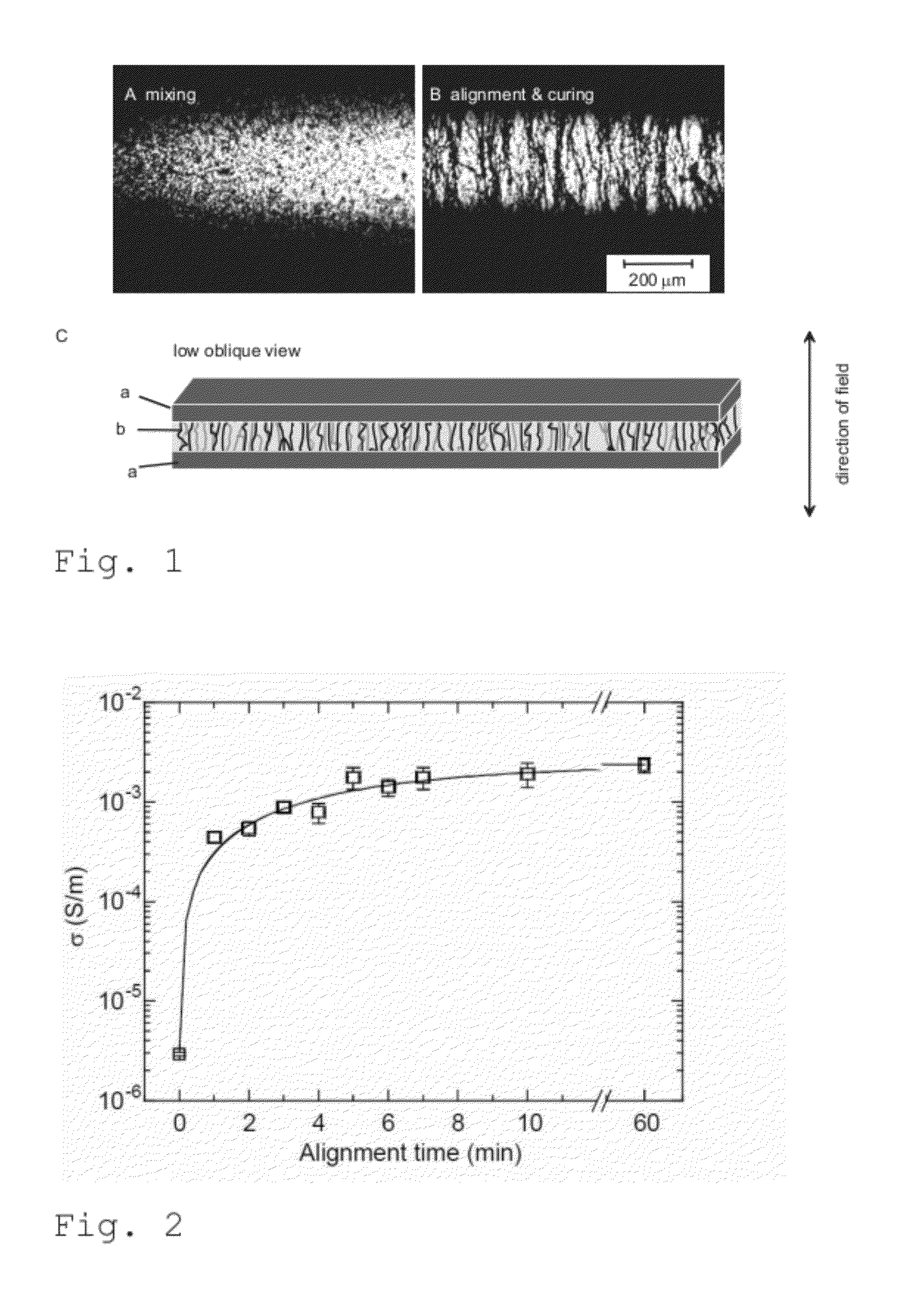
[0180]This example concerns the preparation of a mixture of conductive particles and polymer matrix that in this example is an thermally cured polymer adhesive; as well as determination of conductivity as a function of particle load; and how the step-like increase in conductivity with increasing particle load can be explained by formation of conductive paths between particles when the contacts are formed with increased particle fraction.

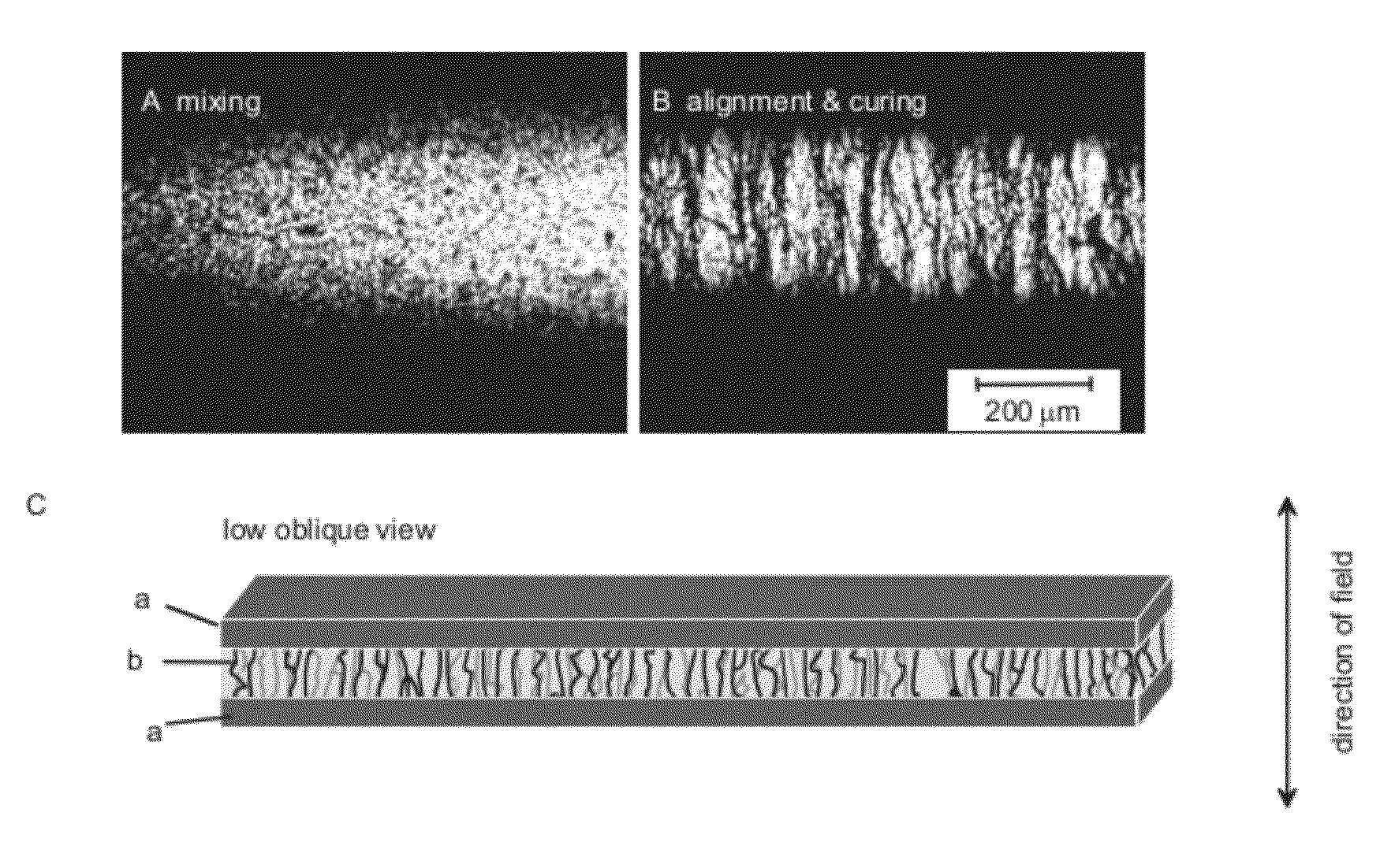
[0181]This example concerns moreover the preparation of the same mixture when the particle load is low, for example 10 times less than the observed percolation threshold, the limit where the isotropic non-aligned mixture is not conductive; as well as the alignment of this mixture using electric field so that the aligned particles form conductive paths resulting in a conductive material, whose conductivity is directional. The example, moreover, shows change of the viscosity of so obtained material, by curing, so that the alignment and directional cond...

example 2

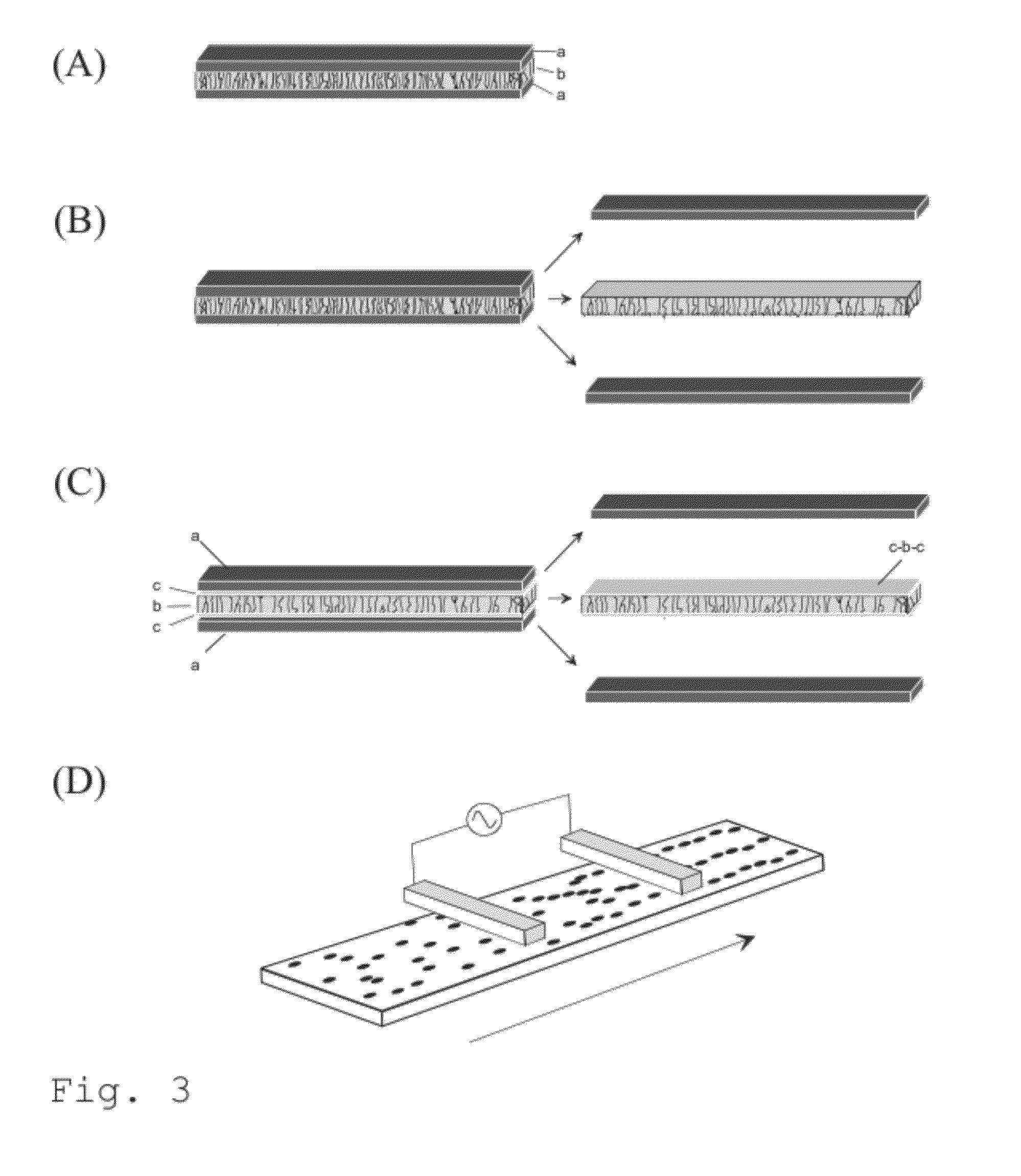
[0193]This example concerns versatile choice of alignment conditions and illustrates how the present invention can be employed not only with electrodes connected to the orientation material but also with electrodes electrically isolated from the material.

[0194]The procedure was otherwise similar to that in example 1, but instead of having material directly connected to the alignment electrodes, the electrodes were electrically disconnected from the material by an insulating layer, for example by 0.127 mm Kapton® foils. Alignment occurred exactly as in Example 1.

[0195]This procedure allows removal of electrodes after alignment and thus freestanding aligned film even in the case where the matrix is adhesive. The alignment also occurs if the electrodes do not touch the material and so the alignment can be performed from the distance. When the material and electrodes are moved, continuous or stepwise, with respect to each others during the alignment, this allows continuous alignment pro...

example 3

[0196]This example concerns the applicability of the alignment method, the use of alignment for particular application of UV-curing. This emphasises the benefit of low particle fraction which makes the material more transparent for UV light for curing.

[0197]The procedure was otherwise similar to that in example 1 or 2 but the thermally cured polymer matrix was replaced by UV-curable Dymax Ultra Light-Weld® 3094 adhesive and the curing step was done by the UV-light with the wavelength 300-500 nm.

[0198]FIG. 4 illustrates the alignment of 0.2 vol-% CNC dispersion in out-of-plane geometry. The mixture was formed following the guideline of example 1 (FIG. 4a) but spread on the alignment electrode using RK Print Paint Applicator that uses a moving bird applicator to level the adhesive layer to the predetermined thickness (the idea is schematically illustrated in FIG. 4b). This admixture was aligned following the method outlined in example 2 but the upper electrode was not in contact with ...


PUM

PropertyMeasurementUnit
electric fieldaaaaaaaaaa
aspect ratioaaaaaaaaaa

Abstract

A method for forming a body comprising a mixture of a matrix and conductive particles, whereby the conductive particles are formed into aligned conductive pathways in an alignment step by applying an electric field between alignment electrodes and thereafter stabilizing the mixture wherein the conductive particles have a low aspect ratio; and a polymeric composition and method for producing such composition which is curable by UV light to an anisotropic electrically conductive polymer layer, comprising i) providing a non-conductive matrix of a flowable polymer composition having inherent photocurability, ii) adding to matrix conductive particles having low aspect ratio in an amount to allow the concentration of the conductive particles to be maintained at a level lower than the percolation threshold, and iii) placing the formed composition in a receptacle where exposure to UV light is prevented, and a method for establishing an anisotropic electrically conductive, optionally thermally conductive

Description

CROSS-REFERENCES TO RELATED APPLICATIONS[0001]This application claims priority to Norwegian patent application No. 20101761, filed Dec. 15, 2010, the contents of which are incorporated herein by reference. This application is also a continuation-in-part of PCT / NO2010 / 000249, filed on Jun. 22, 2010, which claims priority to Norwegian patent application number 20092381, filed Jun. 22, 2009; and a continuation-in-part of PCT / NO2010 / 000241, filed on Jun. 22, 2010, which claims priority to Norwegian patent application number 20092381, filed Jun. 22, 2009; and a continuation-in-part of PCT / NO2010 / 000242, filed on Jun. 22, 2010, which claims priority to Norwegian patent application number 20092381, filed Jun. 22, 2009, the contents of all of which are incorporated herein by reference.BACKGROUND OF THE INVENTION[0002]1. Field of the Invention[0003]The invention concerns a production method for forming an anisotropic conducting polymer body, such as a film or mat, comprising conductive paths...

Claims


Application Information

Patent Timeline
Patent Type & Authority Applications(United States)
IPC IPC(8): B29C65/52H01B1/04H01B1/02H01B13/00H01B13/34B05D5/12H01B1/00H01B1/12B82Y40/00C09D7/61C09D7/65
CPCB82Y30/00C08K7/00H01B1/24B29K2995/0005B29C70/62C08J3/20C08J2300/24C09D5/24C09D7/1291C08K3/04C08K3/08C08K3/22C09J9/02C09J11/04H01B1/22C08K2201/016C08K3/042C09D7/70C09D7/65C09D7/61
Inventor KNAAPILA, MATTIBUCHANAN, MARKHELGESEN, GEIR
Owner CONDALIGN AS
Why Eureka
Try Eureka