[0005]The present invention describes a new type of
cartridge-based microreactor with high internal surface area, exceptional
thermal conductivity, independently controllable temperatures in excess of 400° C. in each microreactor, pressures in excess of 10 MPa, and the ability to perform “
green chemistry” through the use of in-situ aerogels deposited along the length of the reactor.
[0007]Implementations of this aspect of the invention may include one or more of the following The
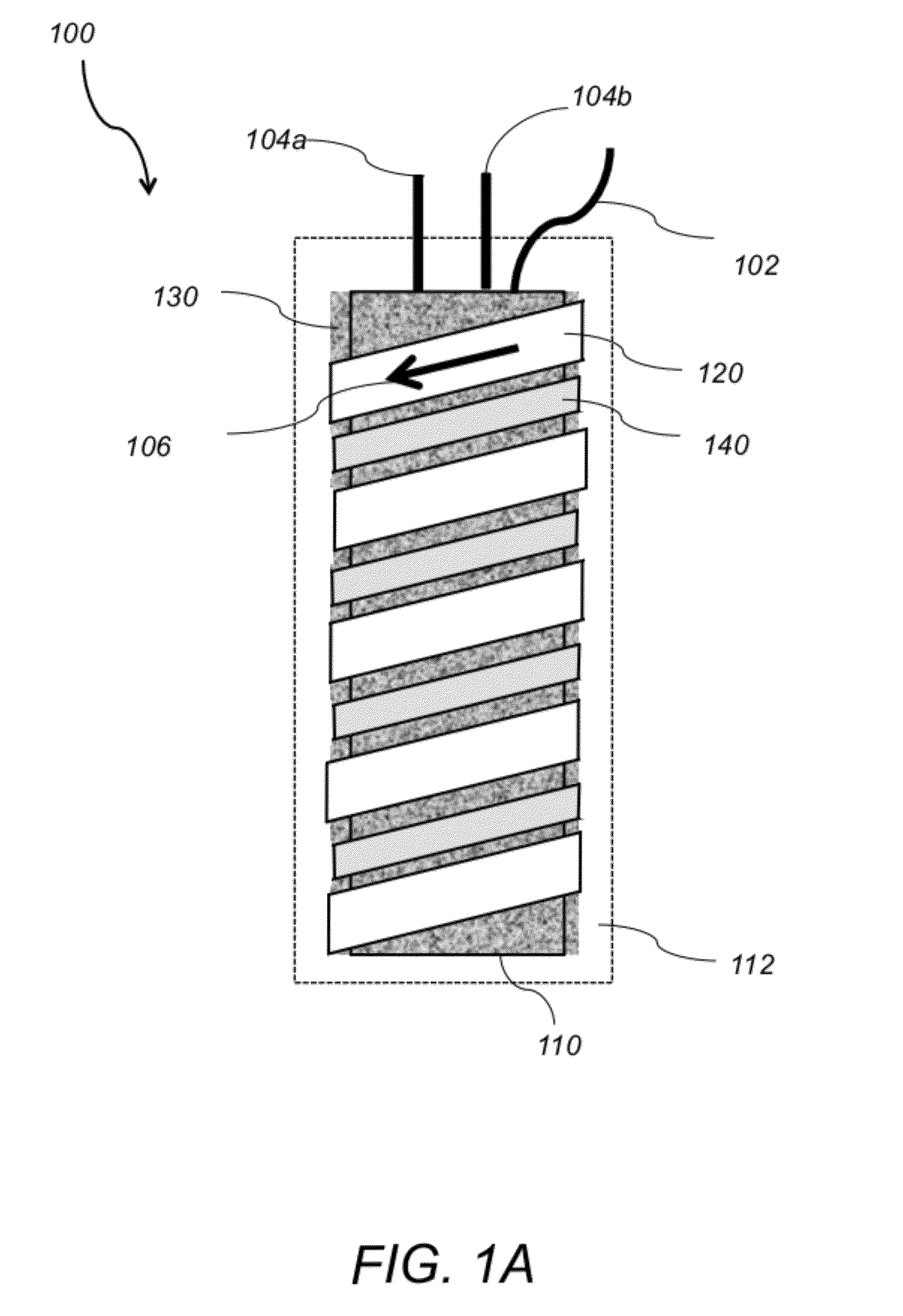
brazing alloy permanently bonds the tubular heater with the metal capillary reaction tubing by first painting the brazing alloy over the metal capillary reaction tubing and the outer heater sheath and then reflowing the brazing alloy by raising the temperature of the microreactor above the brazing alloy's
melting temperature and subsequently solidifying the reflowed brazing alloy by reducing the temperature of the microreactor below the brazing alloy's
melting temperature. The brazing alloy comprises a silver-
nickel brazing alloy paste or a silver solder. The metal capillary reaction tubing comprises a
nickel electroformed tubing, stainless steel tubing or other metal tubing. The metal capillary reaction tubing may include a coated inner surface. The inner surface of the metal capillary reaction tubing may be coated with silica. The silica may be deposited via
atomic layer deposition of
chemical vapor deposition after the metal capillary reaction tubing is installed into the microreactor. The microreactor may further include a cooling line being wrapped around the tubular heater and arranged parallel to the metal capillary reaction tubing. The microreactor may further include an outer insulating layer. The microreactor further includes a
high surface area support uniformly deposited in the inner wall of the metal capillary reaction tubing. The
high surface area support comprises an
aerogel deposited in-situ in the inner wall of the metal capillary reaction tubing. The
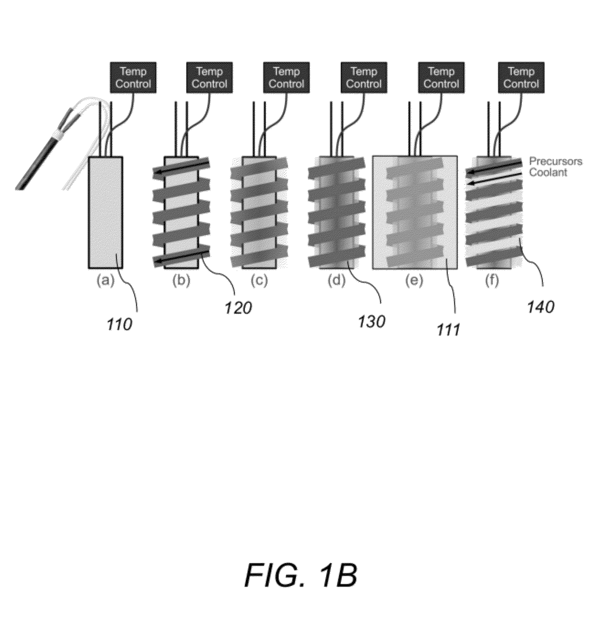
aerogel is uniformly deposited in the inner wall of the metal capillary reaction tubing by first flowing a solution comprising a pre-methanolyzed or partially methanolyzed solution of
nitric acid,
urea, water, and
tetramethyl orthosilicate (TMOS) through the metal capillary reaction tubing, next heating the microreactor to break down the
urea and to produce
ammonium hydroxide, subsequently neutralizing the
nitric acid with the
ammonium hydroxide to produce
ammonium nitrate and to produce a basic solution, next increasing the
reaction rate of condensation with the basic solution thereby resulting in a
polymer-like gel of
amorphous silica and finally removing residual byproducts via
supercritical drying thereby resulting in a uniformly deposited silica
aerogel. The microreactor further includes a small open channel through the center of the deposited aerogel and the open channel reduces the pressure drop across the microreactor, and provides reactant and product exchange with the aerogel via
diffusion. The open channel is formed by threading a narrow carbon filament through the metal capillary reaction tubing and then burning the carbon filament out after the aerogel is deposited.
[0010]Implementations of this aspect of the invention may include one or more of the following features. The tubular heater is permanently bonded with the metal capillary reaction tubing by first painting the brazing alloy over the metal capillary reaction tubing and the outer heater sheath and then reflowing the brazing alloy by raising the temperature of the microreactor above the brazing alloy's
melting temperature and subsequently solidifying the reflowed brazing alloy by reducing the temperature of the microreactor below the brazing alloy's melting temperature. The brazing alloy comprises a silver-
nickel brazing alloy paste or a silver solder. The metal capillary reaction tubing comprises a nickel electroformed tubing, stainless steel tubing or other metal tubing. The metal capillary reaction tubing may include a coated inner surface. The inner surface of the metal capillary reaction tubing may be coated with silica. The silica may be deposited via
atomic layer deposition of
chemical vapor deposition after the metal capillary reaction tubing is installed into the microreactor. The microreactor may further include a cooling line being wrapped around the tubular heater and arranged parallel to the metal capillary reaction tubing. The microreactor may further include an outer insulating layer. The microreactor further includes a
high surface area support uniformly deposited in the inner wall of the metal capillary reaction tubing. The
high surface area support comprises an aerogel deposited in-situ in the inner wall of the metal capillary reaction tubing. The aerogel is uniformly deposited in the inner wall of the metal capillary reaction tubing by first flowing a solution comprising a pre-methanolyzed or partially methanolyzed solution of
nitric acid,
urea, water, and
tetramethyl orthosilicate (TMOS) through the metal capillary reaction tubing, next heating the microreactor to break down the urea and to produce
ammonium hydroxide, subsequently neutralizing the nitric acid with the
ammonium hydroxide to produce
ammonium nitrate and to produce a basic solution, next increasing the
reaction rate of condensation with the basic solution thereby resulting in a
polymer-like gel of
amorphous silica and finally removing residual byproducts via
supercritical drying thereby resulting in a uniformly deposited silica aerogel. The microreactor further includes a small open channel through the center of the deposited aerogel and the open channel reduces the pressure drop across the microreactor, and provides reactant and product exchange with the aerogel via
diffusion. The open channel is formed by threading a narrow carbon filament through the metal capillary reaction tubing and then burning the carbon filament out after the aerogel is deposited. The method further includes depositing a catalyst on the high surface area support via atomic layer deposition.
[0011]Among the advantages of this invention may be one or more of the following. The microreactor
system of the present invention is easy to use in parallel as a catalyst screening system or in series as a small-scale
chemical synthesis system. Catalysts may be deposited onto incorporated aerogels using techniques such as atomic layer deposition (ALD) and co-gelation. The microreactor system also enables “
green chemistry” with
supercritical carbon dioxide as a substitute
solvent for toxic and expensive organic solvents, allows for an arbitrary number of sequential chemical operations each with different
residence times, catalysts, temperatures, and has the ability to add additional reactants between any two stages with minimal
dead space.
[0012]The market for chemicals worldwide is approximately $3T and produces over 70,000 different individual chemicals. Of this market,
specialty and life science chemicals make up approximately 50% of the overall market. These chemicals typically have high values ($1-10 / kg) but often have low total demand per chemical, making it desirable to produce these chemicals in benchtop microreactors as an alternative to traditional reactor designs. With increasing concern for environmental
impact, the ability to move from typical organic solvents to
supercritical carbon dioxide can reduce waste, simplify
processing, and reduce cost.
Continuous production in catalytic microreactors would also allow for efficiency improvements and decreased waste in a broad range of manufacturing environments, especially as compared to chemicals currently manufactured using
batch processing. This technology helps chemical manufacturers operate more safely and more efficiently in both feedstock utilization and in terms of direct energy use.


