Low Temperature Electrolytes for Solid Oxide Cells Having High Ionic Conductivity

Inactive Publication Date: 2013-06-13
FCET
View PDF1 Cites 25 Cited by
  • Summary
  • Abstract
  • Description
  • Claims
  • Application Information

AI Technical Summary

Benefits of technology

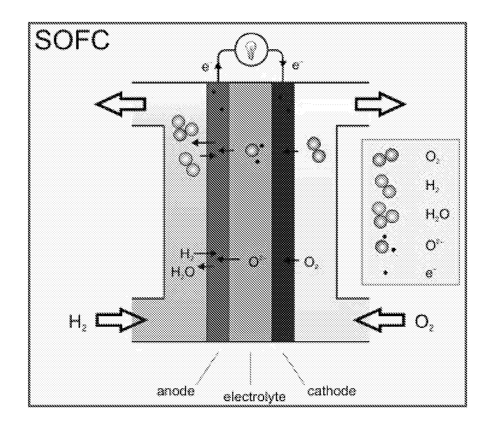
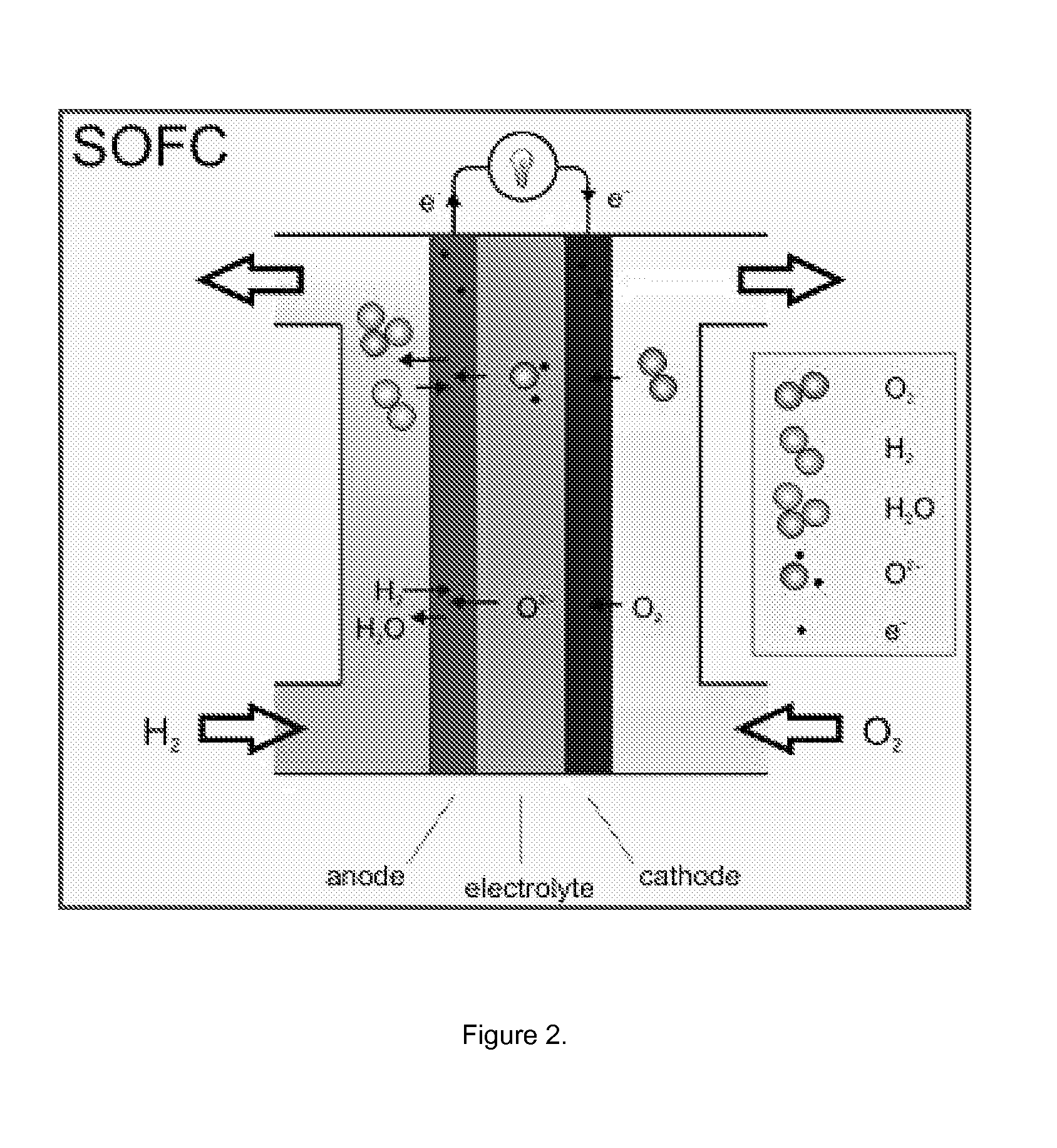
[0027]Certain embodiments of the present invention provide enhanced ionic conductivity through the metal oxide electrolyte, thereby allowing a lower operating temperature. By lowering the operating temperature of a solid oxide cell, less exotic and easier-to-fabricate materials can be utilized in the construction of the cell leading to lower production costs. Thus, some embodiments of the present invention provide solid oxide cells and components thereof employing simpler, less-expensive materials than the current state of the art. For example, if the operating temperature of a solid oxide cell can be lowered, then metals can be used for many different components such as electrodes and interconnects. At these lower operating temperatures, metals have more desirable mechanical properties, such as higher strength, than ceramics. In addition, this higher strength can allow metal components also to have a higher degree of porosity. Current ceramic electrode materials allow for porosity levels in the range of 30% to 40%. Incorporating higher porosity levels in ceramic materials renders them too structurally weak to support cell construction. However, through the use of certain metals or metal carbides, the porosity of an electrode can

Problems solved by technology

The need for exotic materials greatly increases the costs of solid oxide fuel cells, making their use in certain applications cost-prohibitive.
Significantly, the high operating temperature is required because of poor low temperature ion conductivity.
However, high proton conductivity requires precise control of hydration in the electrolyte.
If the electrolyte becomes too dry, proton conductivity and cell voltage drop.
If the electrolyte becomes too wet, the cell becomes flooded.
Electro-osmotic drag complicates hydration control: protons migrating across the electrolyte “drag” water molecules along, potentially causing dramatic differences in hydration across the electrolyte that inhibit cell operation.
In conventional electrolyzers, electrical energy is lost in the electrolysis reaction driving the diffusion of ions through the electrolyte and acr

Method used


Image

  • Low Temperature Electrolytes for Solid Oxide Cells Having High Ionic Conductivity
  • Low Temperature Electrolytes for Solid Oxide Cells Having High Ionic Conductivity
  • Low Temperature Electrolytes for Solid Oxide Cells Having High Ionic Conductivity

Examples


Example

Example 1

[0213]FIG. 3 depicts one embodiment of the invention in the form of a solid oxide cell having a metal oxide electrolyte 380 positioned between a first electrode 310 and a second electrode 320. The metal oxide electrolyte 380 comprises a powder 350 together with a metal oxide 360. In some cases, the powder 350 can be mixed with one or more metal compounds to form a slurry that is then applied by spin coating, brushing, or other suitable method onto the first electrode 310 (or second electrode 320). Then, the metal compound is converted to form the metal oxide 360, for example, by heating the atmosphere about the metal compound, or by inductively heating the first electrode 310. Optionally, once a layer of the metal oxide electrolyte 380 has been formed, additional powder-metal compound slurry can be applied and heated to form a thicker metal oxide electrolyte 380. The cell is assembled by placing the second electrode 320 onto the metal oxide electrolyte 380, or, optionally, ...

Example

Example 2

[0215]FIG. 4 depicts another embodiment of the present invention, in which a first metal oxide 450 and a second metal oxide 460, disposed in interpenetrating domains of metal oxides, form a metal oxide electrolyte between two electrodes 410, 420. To form such domains, a first metal compound composition is applied to the first electrode 410 and converted to a first metal oxide 450, such as, for example, strontium titanate. Then, a second metal compound composition is applied to the first metal oxide 450 and allowed to accumulate in pores, imperfections, and defects in the first metal oxide so formed. The second metal oxide composition is converted to form a second metal oxide 460, such as, for example, yttria-stabilized zirconia. Six alternating layers of the first metal oxide 450 and the second metal oxide 460 are formed in this embodiment.

[0216]In operation, for example, air or other oxygen-containing gas is supplied to the first electrode 410, which acts as the cathode to...

Example

Example 3

[0217]FIG. 5 depicts a solid oxide cell according to one embodiment of the present invention. A nanobar 540 and a metal oxide 560, disposed so that the nanobars 540 orient substantially perpendicularly to a first planar electrode 510, form a metal oxide electrolyte 580 between two electrodes 510, 520. The nanobar 540 can be, for example, a multi-walled carbon nanotube of semiconductor characteristic, oriented in metal oxide 560 which can be, for example, yttria-stabilized zirconia. To make the cell of FIG. 5, chosen nanobars 540 are combined with at least one metal compound in a metal compound composition, that is then applied to the first electrode 510. An orienting force is then applied. Optionally, the first electrode with the metal compound composition is placed in a magnetic field, at least a portion of the nanobars orient due to the magnetic field, and the metal compound composition is converted to form the metal oxide 560. Or, an electric field is applied to orient a...


PUM

PropertyMeasurementUnit
Electrical conductivityaaaaaaaaaa

Abstract

Some embodiments of the present invention provide solid oxide cells and components thereof having a metal oxide electrolyte that exhibits enhanced ionic conductivity. Certain of those embodiments have two materials, at least one of which is a metal oxide, disposed so that at least some interfaces between the domains of the materials orient in a direction substantially parallel to the desired ionic conductivity.

Description

CROSS REFERENCE TO RELATED APPLICATIONS[0001]The present application claims benefit of priority under PCT Article 8 and 35 U.S.C. §119(e) of U.S. Provisional Application No. 61 / 303,003, filed on Feb. 10, 2010, entitled, “LOW TEMPERATURE ELECTROLYTES FOR SOLID OXIDE CELLS HAVING HIGH IONIC CONDUCTIVITY.” That provisional application is incorporated herein by reference in its entirety.STATEMENT REGARDING FEDERALLY-SPONSORED RESEARCH AND DEVELOPMENT[0002]This invention was made with government support awarded by the Department of Energy and administered by Oak Ridge National Laboratory / UT Battelle. The government has certain rights in the invention.FIELD OF THE INVENTION[0003]The present invention relates to electrical energy systems such as fuel cells, electrolyzer cells, and sensors, and, in particular, to solid oxide fuel cells, solid oxide electrolyzer cells, solid oxide sensors, and components of any of the foregoing.BACKGROUND OF THE INVENTION[0004]Solid oxide fuel cells, otherwi...

Claims


Application Information

Patent Timeline
IPC IPC(8): H01M8/12C25B9/00C25B5/00G01N27/28C25B9/19C25B9/23
CPCH01B1/122H01M2300/0091C25B9/00G01N27/28H01M8/1246C25B9/10H01M8/1253H01M8/126Y02E60/521Y02E60/525H01M8/243H01M2008/1293H01M2300/0074H01M2300/0077C25B5/00C25B13/04Y02E60/50Y02P70/50C25B9/19C25B9/23H01M8/0271C04B35/628H01M8/1007G01N27/40G01N27/4073H01M8/004H01M8/1006H01M8/1016H01M2300/0071
Inventor BUDARAGIN, LEONID V.DEININGER, MARK A.POZVONKOV, MICHAEL M.SPEARS, II, D. MORGANFISHER, PAUL D.LUDTKA, GERARD M.PASTO, ARVID E.
Owner FCET
Why Eureka
Try Eureka