Mesoporous titania bead and method for preparing the same

a titania bead and mesh technology, applied in the field of mesh bead, can solve the problems of high cost of silicon solar cells, exhaustion of fossil fuels, etc., and achieve excellent light scattering, high efficiency cells, and increased electron diffusion

Active Publication Date: 2013-06-27
NAT CHENG KUNG UNIV
View PDF3 Cites 5 Cited by
  • Summary
  • Abstract
  • Description
  • Claims
  • Application Information

AI Technical Summary

Benefits of technology

[0010]The inventors were the first to use mesoporous titania beads for manufacturing the photoelectrode of cells, and they surprisingly found that the anatase TiO2 comprised in the mesoporous titania beads and the oriented attachment between crystal grains increased electron diffusion. In addition, the TiO2 beads with submicron-meter size of the present invention resulted in excellent light scattering. With these advantages, the titania bead of the present invention can be used to give high efficiency cells.
[0012]Another object of the present invention is to provide a mesoporous titania bead comprising anatase titania, which provides excellent light scattering.
[0027]The present invention has proved that the properties of titania, such as crystallinity, surface oxygen vacancy concentration and the like, affect diffusion and life span of electrons, thereby affecting charge collection efficiency. And, the size of titania bead apparently affects the efficiency of light harvesting and electron injection, thereby affecting the cell efficiency. The mesoporous titania bead, or the mesoporous titania bead prepared by the method of the present invention, has a proper size, good crystallinity and low surface oxygen vacancy concentration. Moreover, it is also potential to be used as a scattering layer, which is suitable for manufacturing photoelectrode of cells, and enhancing cell efficiency.

Problems solved by technology

After industrial revolution, fossil fuel consumptions grew dramatically accompanying with the development of science, and resulted in fossil fuel exhaustion and environmental damages.
However, lots of energy was consumed during the manufacture of solar cells, so it was still a challenge for solar cells to reach grid parity.
But the cost of silicon solar cells was high because pure crystalline silicon materials were widely used in semiconductor industry.
Materials generally used for non-silicon thin-film solar cells were cadmium telluride (CdTe) or copper indium gallium diselenide (CIGS, CuInGaSe), in which the former material was mainly used by First Solar for manufacturing solar cells with the lowest price per watt in all commercial solar cells, but cadmium contamination was a concerned issue; and the latter material could be used for manufacturing stable solar cells with high efficiency and long life span, but the complicated element composition caused low yield rate.
Generally, DSC had a shorter life span and lower cell efficiency; however, if these disadvantages were overcome, it would be the most widely used solar cell in the future.
However, NPs did not have an oriented structure, and the electrons immigrated in random directions, so the electron collection efficiency was limited.
In addition, the particle size of NPs was too small to produce effective visible light scattering and good light harvesting.
08). Nevertheless, the structure of nanotube and the like did not provide sufficient dye-loading, so the other structures derived from nanoparticles were still under research and develop
However, this two-layer photoelectrode was only applied to rigid DSCs, not introduced into flexible dye-sensitized solar cells (FDSCs).
This was because there were less contacts between large size TiO2 beads and the substrate, so the photoelectrode was not well-attached on the substrate, and this highlighted the disadvantage of FDSCs.
Therefore, the DSCs using TiO2 beads had low electron collection efficiency and reduced cell efficiency.

Method used


Image

  • Mesoporous titania bead and method for preparing the same
  • Mesoporous titania bead and method for preparing the same
  • Mesoporous titania bead and method for preparing the same

Examples


example 1

Analysis of the Titania Products of the Present Invention

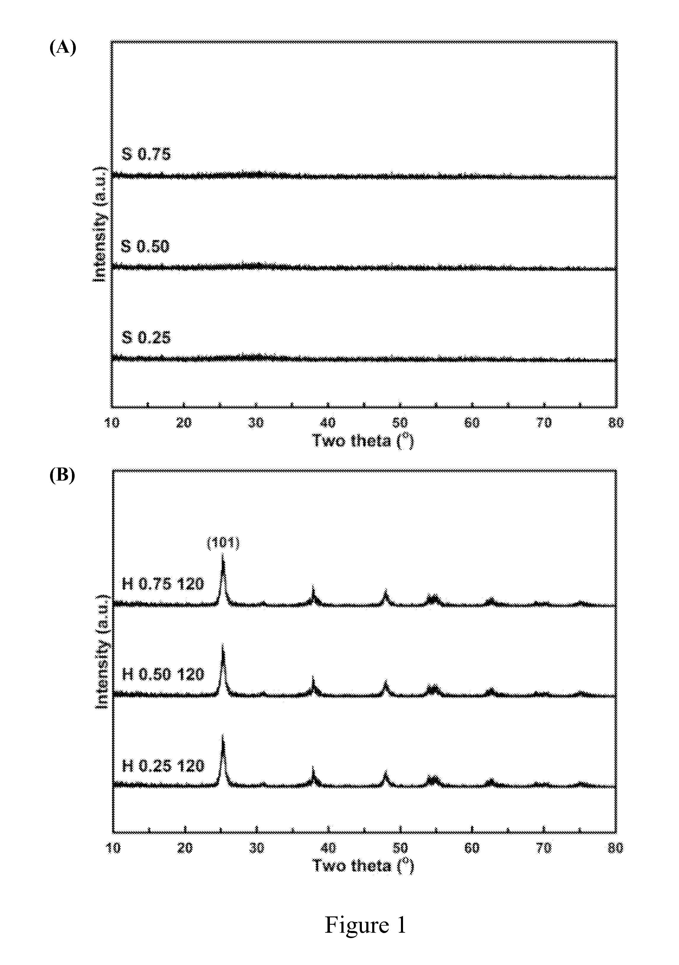
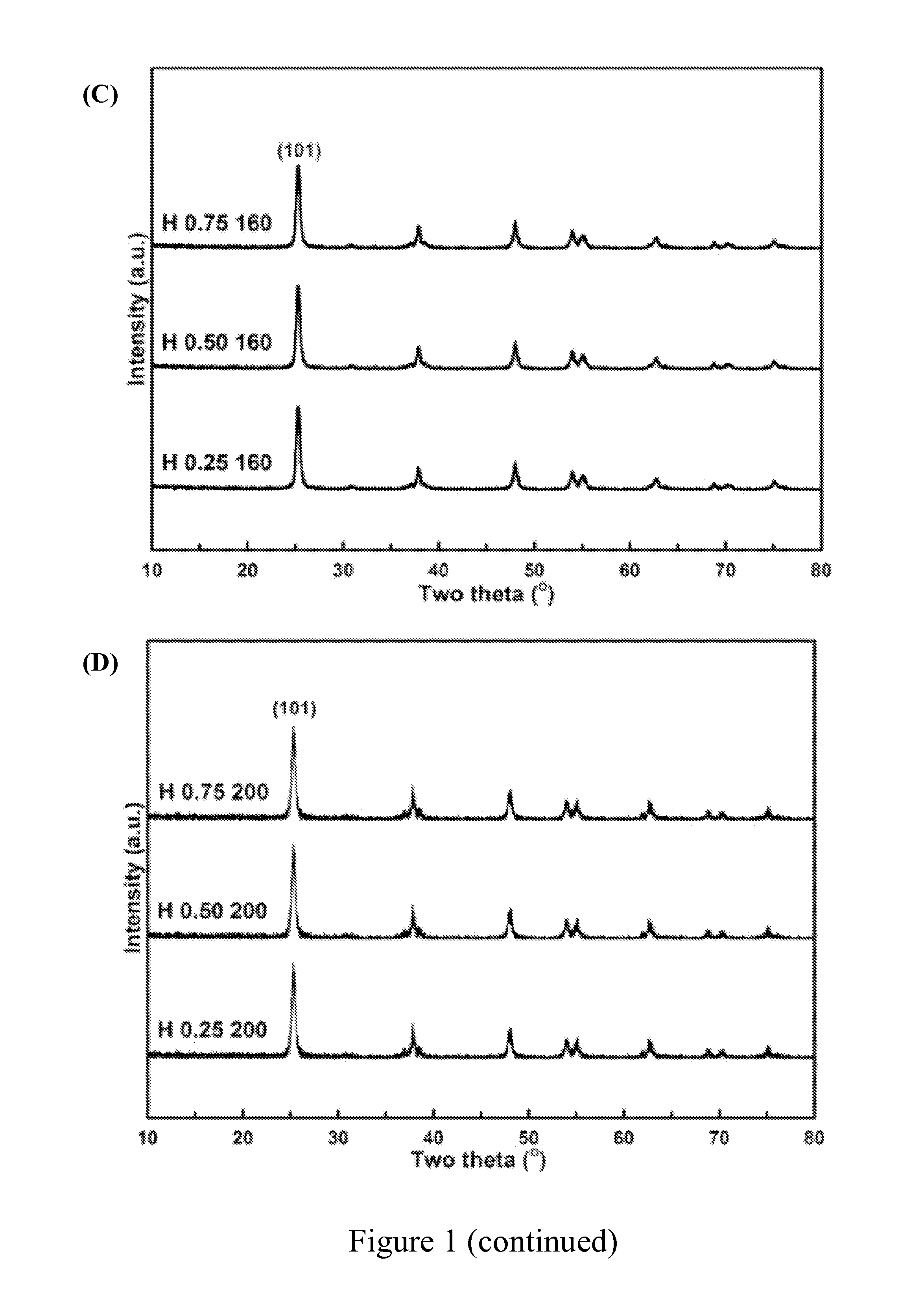
[0048]A series of titania products were prepared by using different amount of steric agent (0.25 g, 0.50 g or 0.75 g) and heating at different temperature (120° C., 160° C. or 200° C.) in water-heating treatment. These titania products were labeled with the letter “H” to show that there were obtained after water-heating treatment. For example, “H 0.25 120” represents the titania product prepared by using 0.25 g of steric agent (hexamine) and heating at 120° C. in water-heating treatment by the preparation method of the present invention.

I. Crystal Structure Analysis of the Titania Product of the Present Invention

[0049]The titania products of the present invention were objected to XRD phase identification and electron microscope analysis to identify if these products had a long-range order crystal structure, namely, the structure of anatase titania.

[0050]First, the titania products of the present invention were separately dried...

example 2

Preparation of Dye-Sensitized Solar Cells with an Electrode Manufactured by Using the Titania Product of the Present Invention and P25 Powder and Efficiency Analysis Thereof

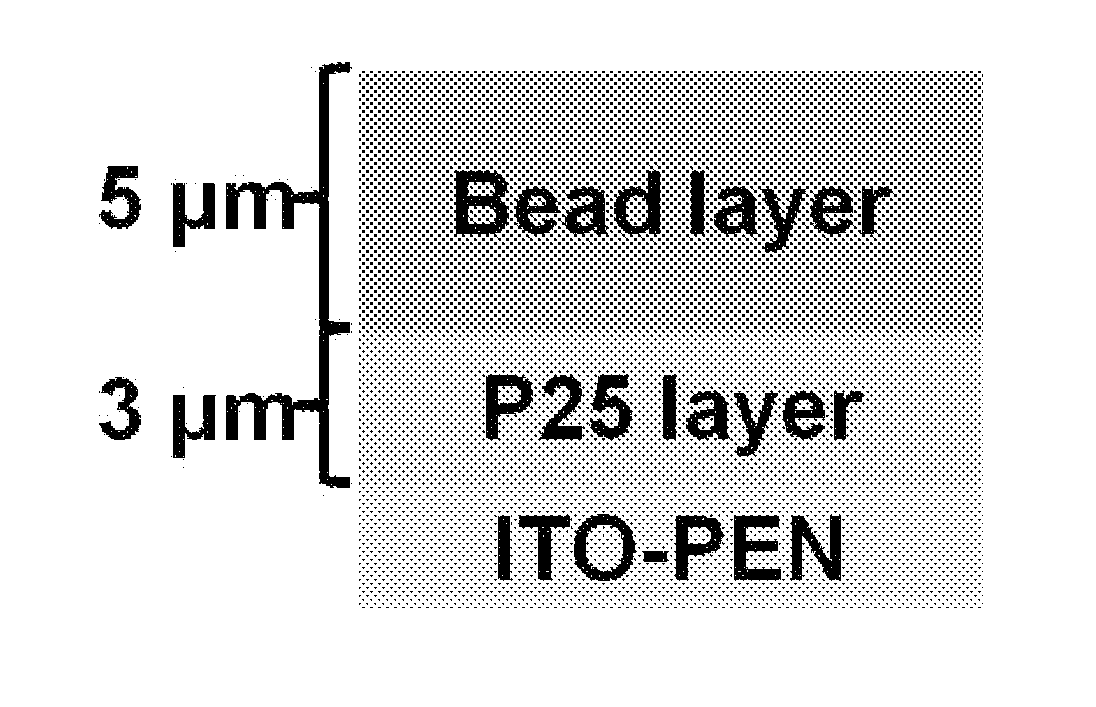
[0066]The dye-sensitized solar cells comprising a photoelectrode shown in Table 6 were manufactured as foresaid. The structure of these photoelectrodes is shown in FIG. 5(A), which is a well-known structure of dye-sensitized solar cells, comprising two layers made of titania, wherein the first one is scattering layer (bead layer) and the second one is a titania nanoparticle layer (P25 layer). In Table 6, photoelectrode A merely comprised a titania nanoparticle layer composed of pure P25, no scattering layer was comprised. Photoelectrode B comprised a titania nanoparticle layer composed of pure P25 and a scattering layer composed by pure P25, so it was substantively equal to a pure P25 nanoparticle layer of 8 μm. In photoelectrode C-G, the second layer was composed of the titania products of the present invention,...

example 3

Preparation of Dye-Sensitized Solar Cells with an Electrode Manufactured by Using the Titania Product of the Present Invention Alone and Efficiency Analysis Thereof

[0073]The dye-sensitized solar cells comprising a photoelectrode shown in Table 7 were manufactured as foresaid, wherein the structure of these photoelectrodes is shown in FIG. 5(B). Photoelectrode 0 was composed of the nanoparticle H 0.25 200, which was not in form of bead. Photoelectrodes H-N were prepared by using the mesoporous titania bead of the present invention alone. Sample B was the control. The labels of the titania products of the present invention are as foresaid described.

TABLE 7Result of titania layers of photoelectrode prepared by usingthe titania product of the present invention alonethick-BeadCellPhoto-nesssizeDye loadingefficiency ηSampleelectrode(μm)(nm)(×10−7 mol / cm2)(%)BP258—2.374.29HH 0.75 1207.53755.603.16IH 0.75 1602.77501.902.63JH 0.75 1605.27503.643.69KH 0.75 1607.87505.484.03LH 0.75 16010.07506...


PUM

PropertyMeasurementUnit
pore radiusaaaaaaaaaa
porosityaaaaaaaaaa
specific surface areaaaaaaaaaaa

Abstract

The present invention relates to a mesoporous titania bead and the preparation method thereof, wherein said mesoporous titania bead has a diameter of 200-1000 nm, specific surface area of 50-100 m2 / g, porosity of 40-60%, pore radius of 5-20 nm, pore volume of 0.20-0.30 cm3 / g, and the titania comprised in the bead is anatase titania.

Description

BACKGROUND OF THE INVENTION[0001]1. Field of the Invention[0002]The present invention relates to a mesoporous titania bead and the preparation method thereof.[0003]2. Description of the Related Art[0004]After industrial revolution, fossil fuel consumptions grew dramatically accompanying with the development of science, and resulted in fossil fuel exhaustion and environmental damages. For sustainable survival, the development of renewable and alternative energy was the ultimate goal of the world. In all alternative energies, solar energy caught people's attention because it was abundant and clean, and many companies had invested in the associated research and development.[0005]Solar cell, also called photovoltaic cell, was a device for converting light energy into electrical energy. However, lots of energy was consumed during the manufacture of solar cells, so it was still a challenge for solar cells to reach grid parity. At present, most commercial solar cells were silicon solar cel...

Claims


Application Information

Patent Timeline
Patent Type & Authority Applications(United States)
IPC IPC(8): C01G23/08C01G23/047
CPCC01G23/053C01G23/0536H01G9/2031C01P2002/72C01P2004/03Y10T428/2982C01P2004/62C01P2006/12C01P2006/14C01P2006/16Y02E10/542C01P2004/04Y02P70/50
Inventor TING, JYH-MINGKE, CHUN-REN
Owner NAT CHENG KUNG UNIV
Why Eureka
Try Eureka