Method and system for production of silicon and devicies

a production method and technology of silicon, applied in the direction of silicon compounds, lighting and heating apparatuses, furnaces, etc., can solve the problems of single successful experiment on this approach, low production yield, and unfavorable direct reaction between silicon and hydrogen, so as to reduce the cost, reduce the reaction temperature, and enhance the reaction rate of silane formation

Inactive Publication Date: 2013-08-01
CHU XI
View PDF0 Cites 7 Cited by
  • Summary
  • Abstract
  • Description
  • Claims
  • Application Information

AI Technical Summary

Benefits of technology

[0008]In one embodiment of the invention, silane and hydrogen (optionally with inert gas) mixtures are produced using catalytic gasification of Si-materials including elemental silicon, silicon alloys and Si-containing compounds with a hydrogen source such as hydrogen gas, atomic hydrogen and / or hydrogen ions (proton). With the presence of catalyst, the reaction temperature can be greatly reduced and the reaction rate of silane formation can be enhanced. The gas mixtures (silane and hydrogen, with inert gas) may be co-purified simultaneously to remove phosphor (P) and boron (B) compounds and other harmful impurities (without separating silane from hydrogen or inert gas). The co-purified mixture is then fed for downstream applications. This can greatly reduce the cost of, and simplify the manufacturing process of silane thus the down stream applications.

Problems solved by technology

However, the direct reaction between silicon and hydrogen is thermodynamically unfavorable except at ultra-high temperatures and ultra-high pressures (up to 2000° C. and 1000 atms).
Another challenge is, at a high temperature greater than 300° C., silane tends to decompose back into silicon fine soots and hydrogen making the production yield extremely low.
So far not a single successful experiment on this approach has been reported yet.

Method used


Image

  • Method and system for production of silicon and devicies
  • Method and system for production of silicon and devicies
  • Method and system for production of silicon and devicies

Examples


example 1

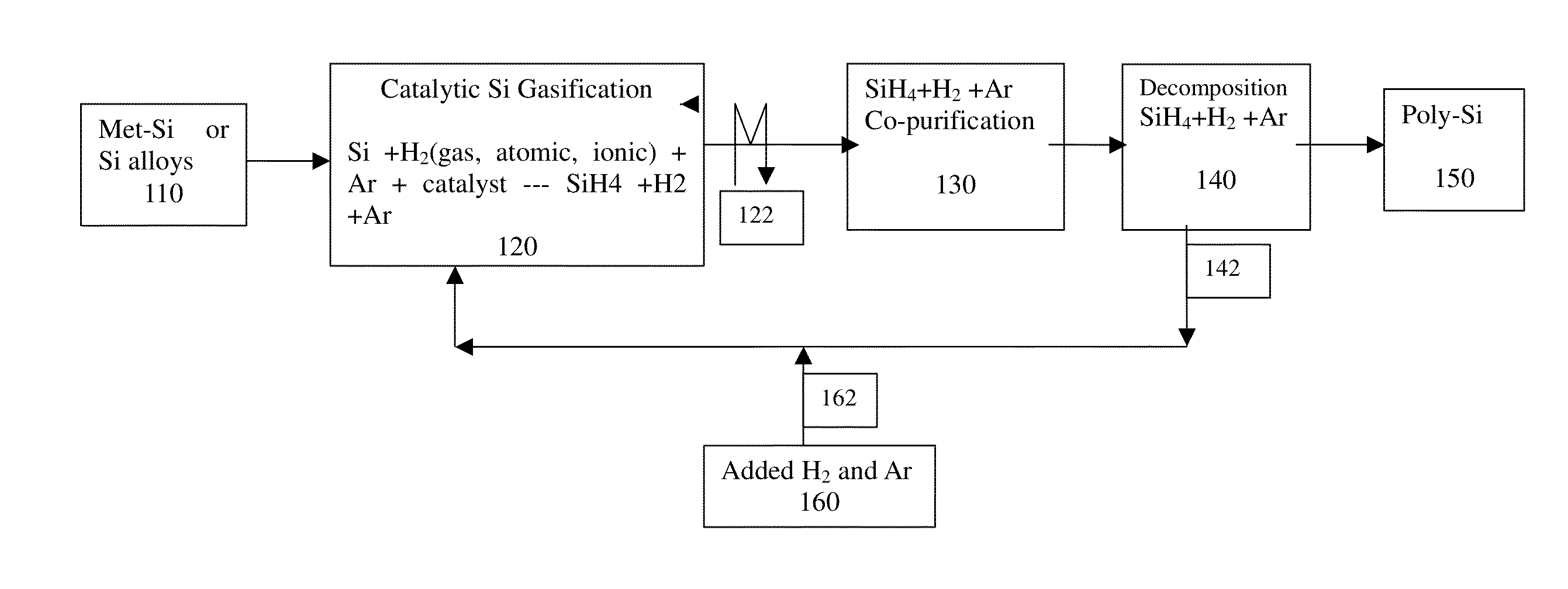
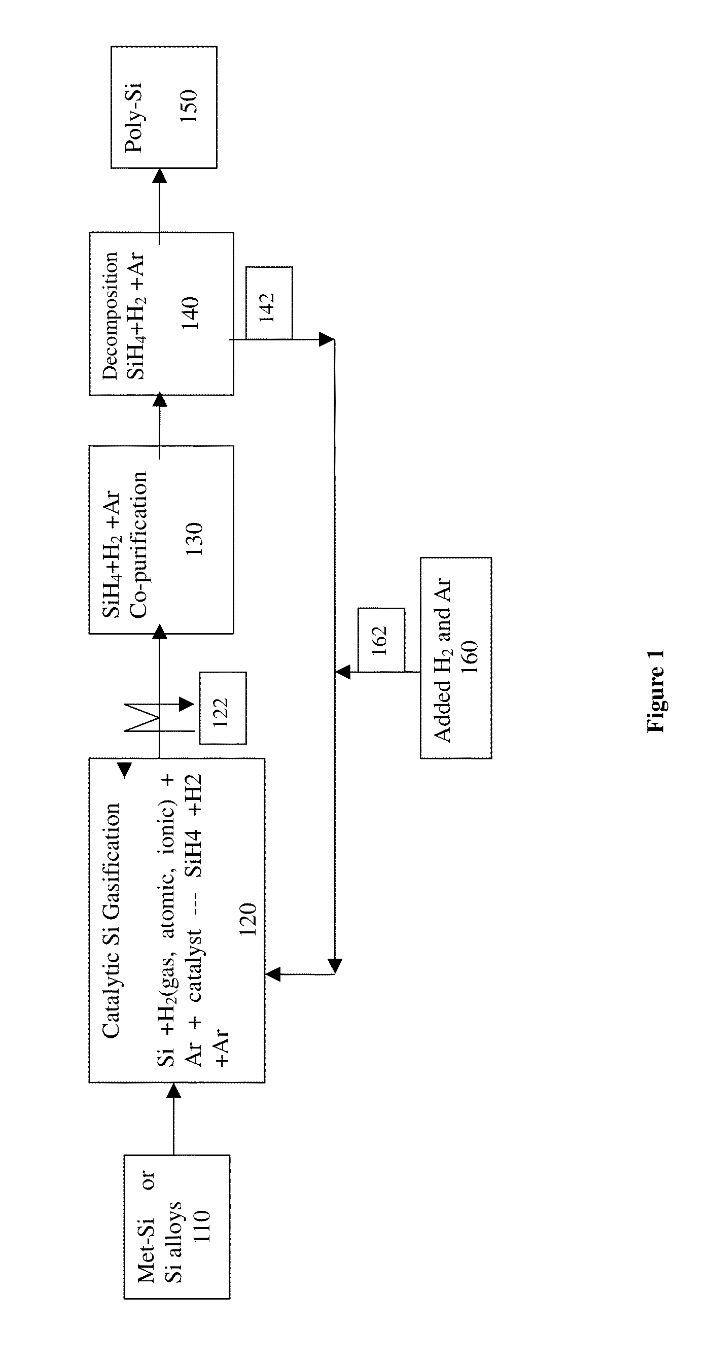
Catalytic Gasification of Metallurgical Silicon Using Hydrogen Gas

[0114]2.0 wt % Cu, and 1 wt % Ni catalyst (using chlorides) is loaded onto met-silicon powder 100-30 mesh through solution impregnation or coating. After drying, silicon powder is heated in a fluidized bed reactor, a spouted bed and a packed bed reactors respectively in flow of chemical pure hydrogen at 900-1300° C. respectively. As shown in FIG. 5b, orange color flame was observed by the burning of the tail gas from the reactor indicating the formation of silane. In addition, the weight of silicon powder is noticeably reduced after 10 hours of reaction. The tail gas from the reactor is also quenched very quickly to about 500 C. or lower, or 300 C. or lower by passing the tail gas to a heat exchanger with a circulating coolant. In comparison, same amount of metallurgical silicon without catalyst is heated under the same conditions, and no mass loss of silicon is detected.

example 2

Catalytic Hydrogen Gasification on the Surface of Single Crystal Silicon

[0115]To gain microscopic understanding of silicon gasification, a single crystal 100 wafer is chosen and divided into two pieces sample A and sample B respectively. A few droplets of palladium acetate solution (with acetone) is sprayed on the surface of sample A. After drying, the wafer was broken into small pieces and heated in hydrogen at various temperature for a series of time intervals. In each case, a small piece of sample B is used as a control sample. After the reaction, each sample was examined under a scanning electron microscope (SEM) for surface morphology.

[0116]FIG. 7 shows a SEM micrograph of a Pd catalytically etched sample A single crystal surface after heating in hydrogen at 900° C. for 30 minutes. It can be seen that Pd forms catalyst particles as indicated as 711, 712, and 716, during the gasification reaction, the particles move on the single crystal surface, meanwhile they create channels (...

example 3

[0117]Gasification of silicon by plasma generated atomic hydrogen using a commercial DC plasma torch, with hydrogen being used to form a hydrogen plasma in a fluidized bed reactor, a spouted bed and a packed bed reactors respectively generating orange color flames and golden deposit on the down stream wall indicating the formation of silane.

Example 4

[0118]Gasification of silicon by plasma generated atomic hydrogen using a commercial ICP plasma torch, with hydrogen being used to form a hydrogen plasma in a fluidized bed reactor, a spouted bed and a packed bed reactors respectively generating orange color flames and golden deposit on the down stream wall indicating the formation of silane.


PUM

PropertyMeasurementUnit
temperatureaaaaaaaaaa
temperaturesaaaaaaaaaa
temperatureaaaaaaaaaa

Abstract

In one embodiment of the invention, the silane and hydrogen (and inert gas) mixture is produced using catalytic gasification of silicon (or si-containing compounds including silicon alloys) with a hydrogen source such as hydrogen gas, atomic hydrogen and proton. By not separating silane from hydrogen and co-purifying all the gases (silane and hydrogen, inert gas) in the gas mixture simultaneously, the mixture is co-purified and then provide feed stock for downstream application without further diluting the silane gas. One aspect of the invention addresses the need for an improved production method, apparatus and composition for silane gas mixtures for large scale low cost manufacturing of high purity silicon and distributed on-site turnkey applications including but not limited to the manufacture of semiconductor integrated circuits, photovoltaic solar cells, LCD-flat panels and other electronic devices. Thus, various embodiments of the invention can greatly reduce the cost and simplify the process of manufacturing silicon.

Description

RELATED APPLICATIONS[0001]This application claims the benefit of priority, under 35 U.S.C. §119(e) to U.S. Provisional Patent Application Ser. No. 61 / 632,663, filed on Jan. 28, 2012, entitled METHODS AND SYSTEMS FOR THE PRODUCTION OF SILICON AND DEVICES, and is a continuation application of prior U.S. patent application entitled REACTOR AND METHOD FOR CONVERTING SILICON GAS filed on Jan. 19, 2012 based on International Application Number PCT / CN2010 / 075252 filed on Jul. 19, 2010; which the international patent application claims the benefit of priority, under 35 U.S.C. §119 to Chinese Patent Application Serial Number 200910159609.2, filed on Jul. 19, 2009; and Chinese Patent Application Serial Number 200910166276.6, filed on Aug. 8, 2009, the entire contents of which are incorporated herein by reference in their entirety.FIELD OF THE INVENTION[0002]The present invention relates to a process method, composition and system for catalytic gasification of silicon materials including eleme...

Claims


Application Information

Patent Timeline
Patent Type & Authority Applications(United States)
IPC IPC(8): C01B33/039
CPCC01B33/039C01B33/029B01J2208/00318B01J2219/0886B01J2219/0816B01J2219/0822B01J2219/0871B01J19/088
Inventor CHU, XI
Owner CHU XI
Why Eureka
Try Eureka