
Lithium battery with silicon-based anode and silicate-based cathode

a technology of silicon-based anodes and lithium-ion batteries, which is applied in the direction of cell components, final product manufacturing, sustainable manufacturing/processing, etc., can solve the problems of loss of capacity and rate capability, loss of 10 to 50% of available lithium ions, and cycle irreversibility, and achieve excellent cycling efficiencies, high energy capacity, and enhanced cycling efficiency of silicon and carbon nanofiber composite negative electrodes

Active Publication Date: 2013-09-12
GENERAL MOTORS COMPANY
View PDF9 Cites 24 Cited by
  • Summary
  • Abstract
  • Description
  • Claims
  • Application Information

AI Technical Summary

Benefits of technology

The patent text describes a method for operating a lithium-ion battery using a cathode made of flake-like silicate materials combined with silicon-coated carbon nanofibers. This method helps to reduce the initial cycle irreversibility of the lithium ions and improves the efficiency of the battery.

Problems solved by technology

With respect to lithium ion batteries, there is a loss of capacity and rate capability because after the initial charge / discharge cycles of new batteries, there is an “initial cycle irreversibility” or a loss of 10 to 50% of available lithium ions.
Thus, the initial cycle irreversibility decreases storage capacity of the battery for subsequent charges and discharges.
However, these compensations and alternate electrode systems have shortcomings and provide technical barriers for commercialization of an optimized battery.
Current positive electrode materials are limited to a maximum capacity between 100-200 Ah / kg in practical lithium cells.
The positive electrode decomposition impacts cell performance and may lead to battery thermal run-away.
Furthermore, transition metals like cobalt and nickel used in oxide positive electrodes significantly increase cost.
Further, phosphate positive electrodes have an intrinsically large band gap and, therefore, require a specialized coating (with carbon) or doping that adds to the overall cost.
In addition, most oxide cathodes suffer from dissolution of transition metals such as manganese, particularly at elevated temperatures that limits their applications.
Further, the oxide cathode acts as catalyst on electrolyte decomposition at high state of charge, causing increase in cell impedance.

Method used


Image

  • Lithium battery with silicon-based anode and silicate-based cathode
  • Lithium battery with silicon-based anode and silicate-based cathode
  • Lithium battery with silicon-based anode and silicate-based cathode

Examples


Embodiment Construction

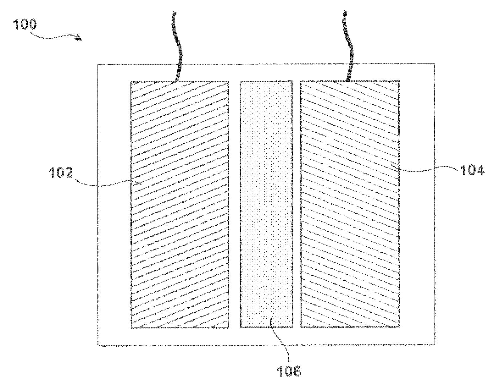
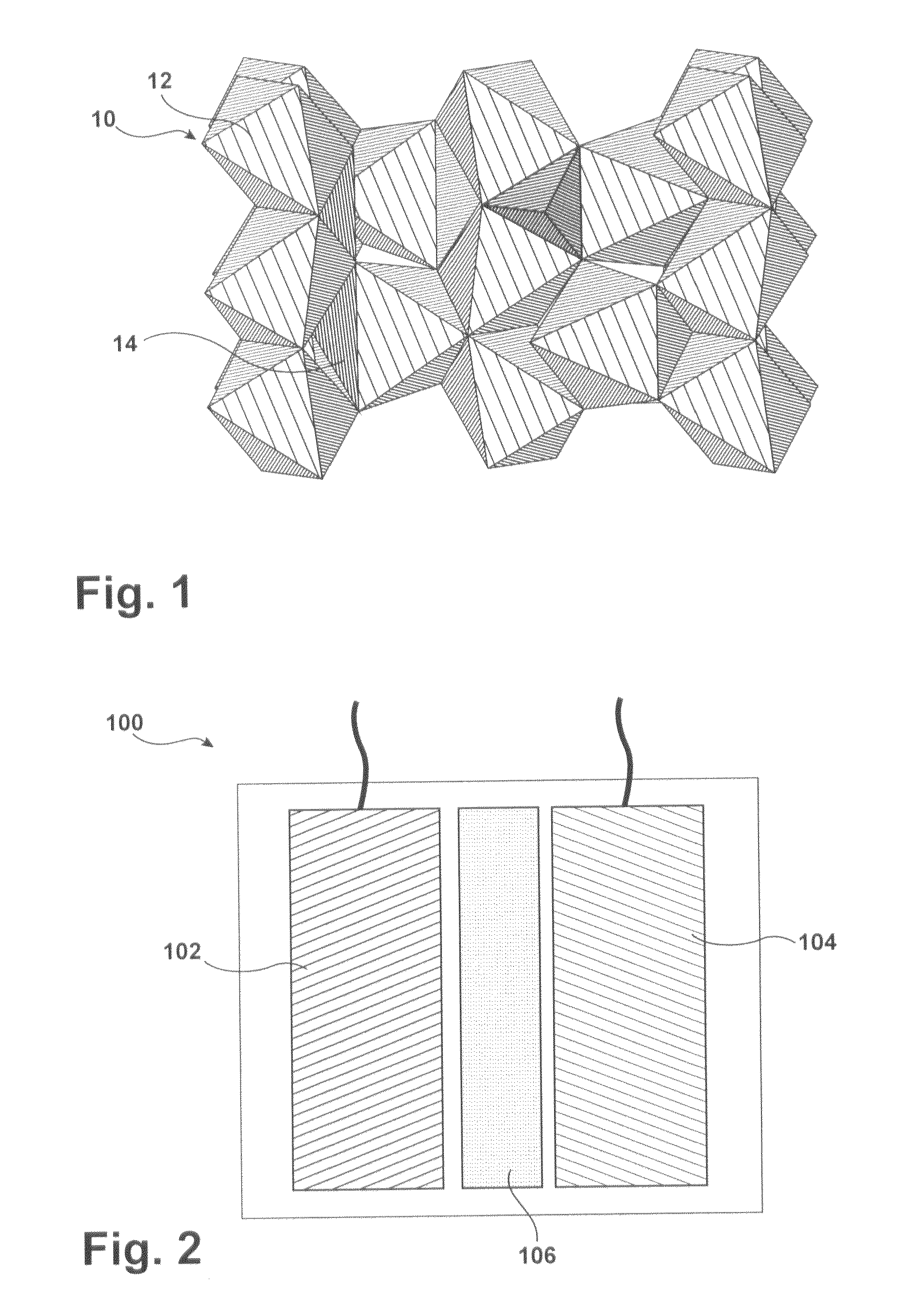
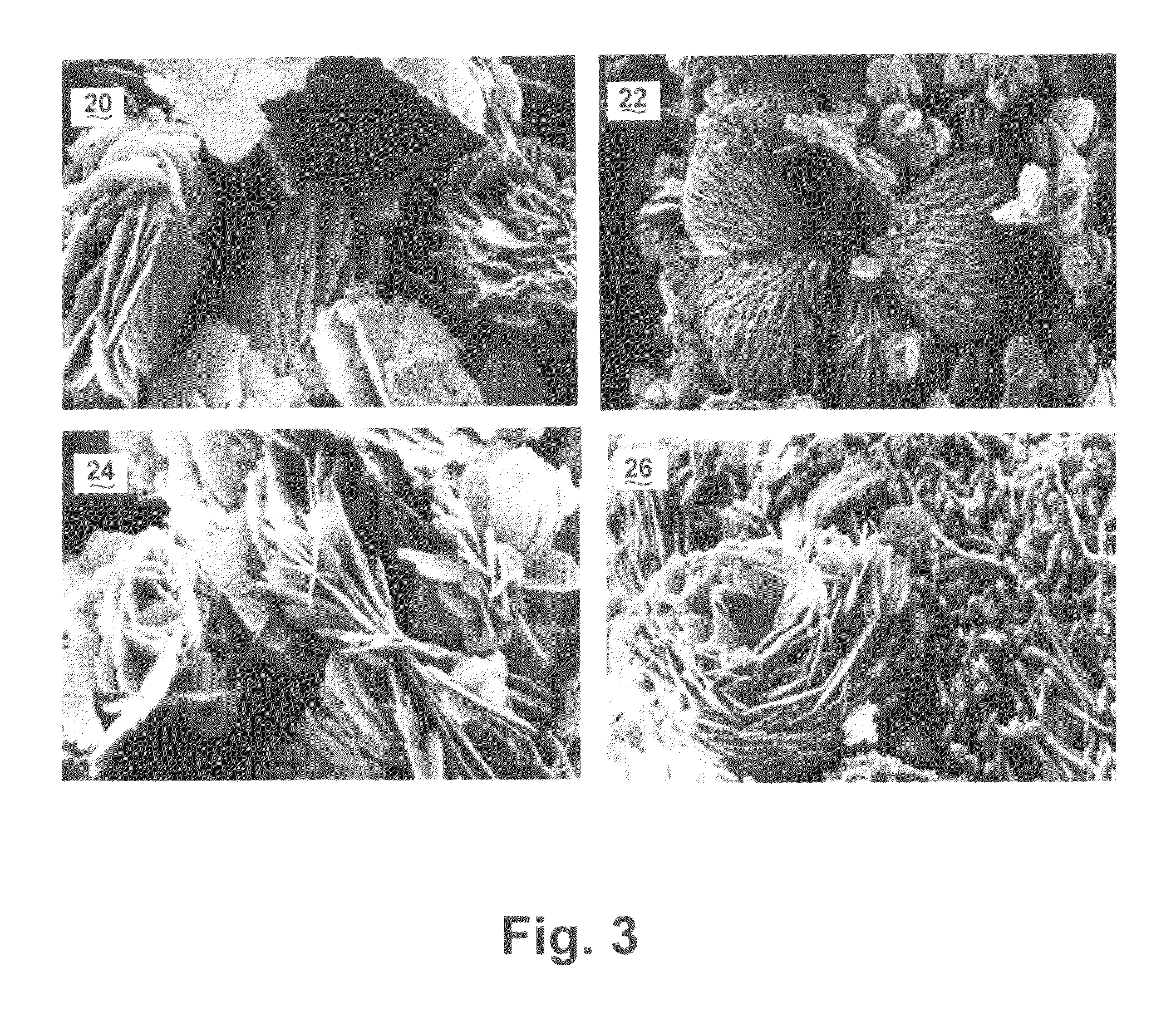
[0075]Silicate-based positive electrodes were synthesized using unique preparation methods to form the proper particle crystal structure, composition, size and morphology (platelet with optimized Li+ diffusion pathway). Among the various silicate structures, those with proper ratios of mixed metal / SiO4 (Li2MSiO4, M=mixed multi-redox transition metal centers) were synthesized to further enhance their energy storage capacity and maximize the number of redox electron exchanges and the available sites for lithium ions. The voltage profile of the silicate was tuned by proper selection of mixed transition metals, lattice parameters, and silicate anion packing density. By using a polyol process with a low cost surfactant, a single phase, pure Li2MnSiO4 with rose-flower geometry, having thin sheet layer silicate with sheet thickness of about 10 nanometers was created. The scanning electron microscopy (SEM) results favored flake-like structures.

[0076]The electrical and ionic conductivity of ...


PUM

PropertyMeasurementUnit
thicknessaaaaaaaaaa
thicknessaaaaaaaaaa
thicknessaaaaaaaaaa

Abstract

A lithium-ion battery is provided and related methods. The lithium-ion battery includes an electrode comprising an Olivine flake-like structure and an electrode comprising a plurality of coated carbon nanofibers. The Olivine flake-like structures form clusters through which the lithium ions are transported while reducing initial cycle irreversibility. The electrode comprising the coated carbon nanofibers additionally reduce initial cycle irreversibility by controlling expansion of the substrate forming the electrode comprising the coated carbon nanofibers.

Description

CROSS-REFERENCE TO RELATED APPLICATIONS[0001]This application claims the benefit of U.S. Provisional Application No. 61 / 608,262, filed on Mar. 8, 2012. The disclosure of the above application is incorporated herein by reference in its entirety.[0002]This application claims the benefit of U.S. Ser. No. 13 / 409,732 filed Mar. 1, 2012, which claims priority to U.S. Provisional Application No. 61 / 450,401, filed on Mar. 8, 2011; and U.S. Ser. No. 13 / 409,709 filed Mar. 1, 2012, which claims priority to U.S. Provisional 61 / 450,411, filed on Mar. 8, 2011. The entire disclosures of each of the above applications are incorporated herein by reference.FIELD[0003]The present disclosure relates to lithium batteries having a silicon-based anode and a silicate-based cathode.BACKGROUND[0004]The background description provided herein is for the purpose of generally presenting the context of the disclosure. Work of the presently named inventors, to the extent it is described in this background section,...

Claims


Application Information

Patent Timeline
Patent Type & Authority Applications(United States)
IPC IPC(8): H01M4/583H02J7/00H01M10/0525B82Y30/00
CPCH01M4/134H01M4/136Y02E60/122Y10T29/49108H01M4/5825H01M4/583H01M10/0525H01M4/139Y02E60/10Y02P70/50
Inventor NAZRI, GHOLAM-ABBAS
Owner GENERAL MOTORS COMPANY
Learn More