Method and Apparatus for Improved Firing of Biomass and Other Solid Fuels for Steam Production and Gasification

a biomass and solid fuel technology, applied in the direction of lighting and heating apparatus, fire-box steam boilers, combustion types, etc., can solve the problems of high cost of erection, and difficulty in and achieve rapid and preferably independent control of the supply of fuel. , the effect of reducing the temperature variation of the furna

Inactive Publication Date: 2013-10-24
SULLIVAN HIGGINS & BRION PPE LLC
View PDF18 Cites 6 Cited by
  • Summary
  • Abstract
  • Description
  • Claims
  • Application Information

AI Technical Summary

Benefits of technology

[0010]In some embodiments, fuel falls into one or more troughs at the bottom of the boiler, with each trough lined with an insulating material and refractory material, so that the structure acts to reduce temperature variations in the furnace. In some embodiments, a fuel supply located on top of the boiler along with along with a fuel feed system enables rapid and preferably independent control of the supply of fuel to different portions of the furnace. In some embodiments, the boiler is composed of modules that can be easily transported for assembly on site. In some embodiments, an array of chamber walls facilitates more efficient heat transfer from the combustion gases to improve steam generation.

Problems solved by technology

A “hung” boiler typically may require a very strong and expensive structure to support the boiler.
One of the biggest problems with current boiler design is the cost of erection.
This frequently takes much longer and may be much more expensive than anticipated, driving up the actual cost of the boiler.
Boilers as described above have been in use for many years and the technology is very mature, but they are very expensive and have significant operational limitations.
Grate fired boilers and fluidized bed boilers are limited in the temperatures they can tolerate in the lower furnace otherwise they will over heat the grate or sand bed.
They also do a poor job of mixing the combustion air and pyrolysis gasses above the bed because the air flow arrangement is dictated by the requirements to cool the grate or fluidize the sand bend.
This leaves little setup flexibility to improve combustion in the boiler.
Mechanical grates suffer from poor reliability and fluidized bed boilers suffer from excessive sand erosion and sand agglomeration.

Method used


Image

  • Method and Apparatus for Improved Firing of Biomass and Other Solid Fuels for Steam Production and Gasification
  • Method and Apparatus for Improved Firing of Biomass and Other Solid Fuels for Steam Production and Gasification
  • Method and Apparatus for Improved Firing of Biomass and Other Solid Fuels for Steam Production and Gasification

Examples


Embodiment Construction

[0018]Various embodiments of the present invention include several novel features that can significantly reduce the capital cost of the boiler while further improving the ability to burn difficult fuels.

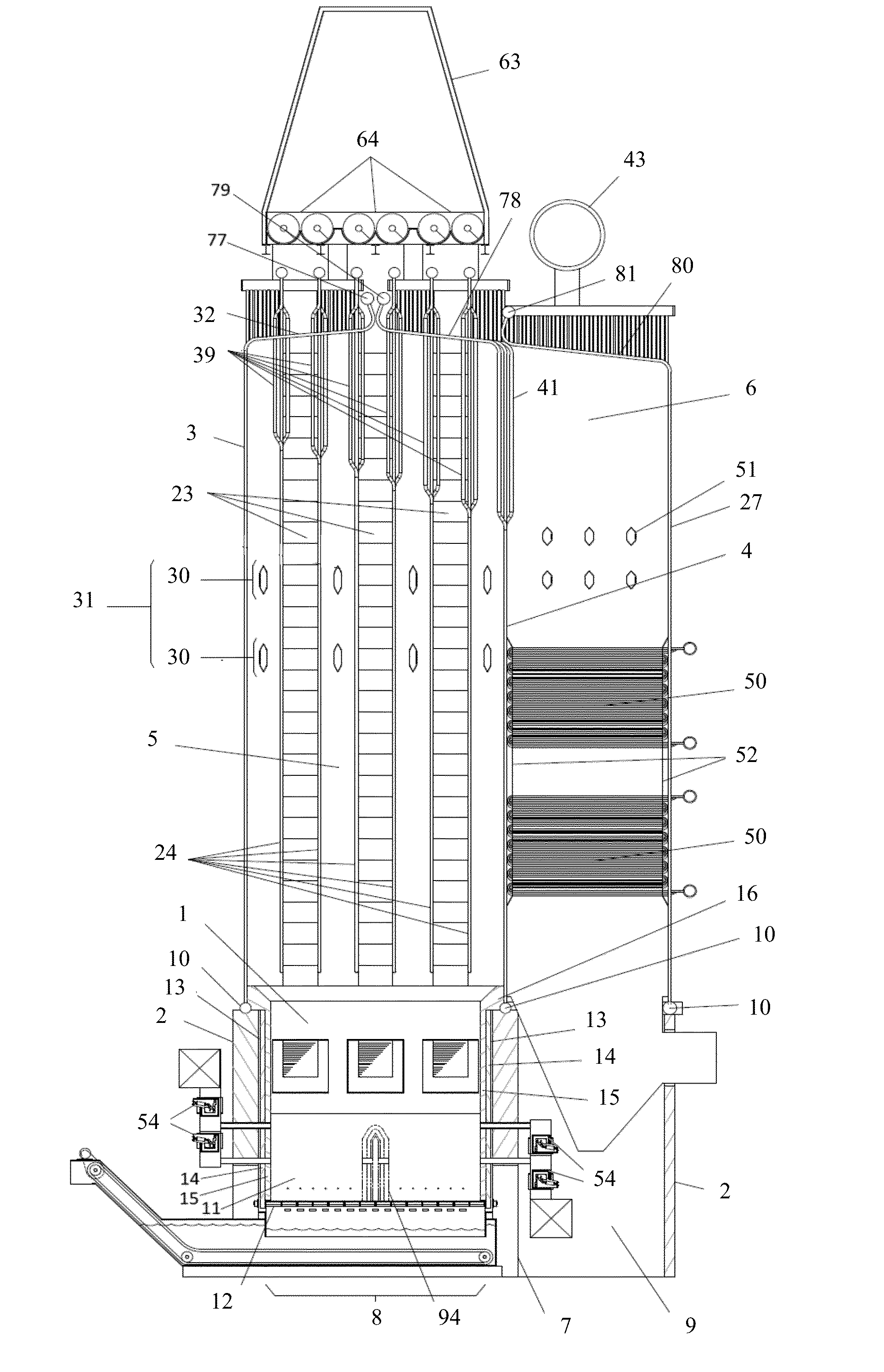
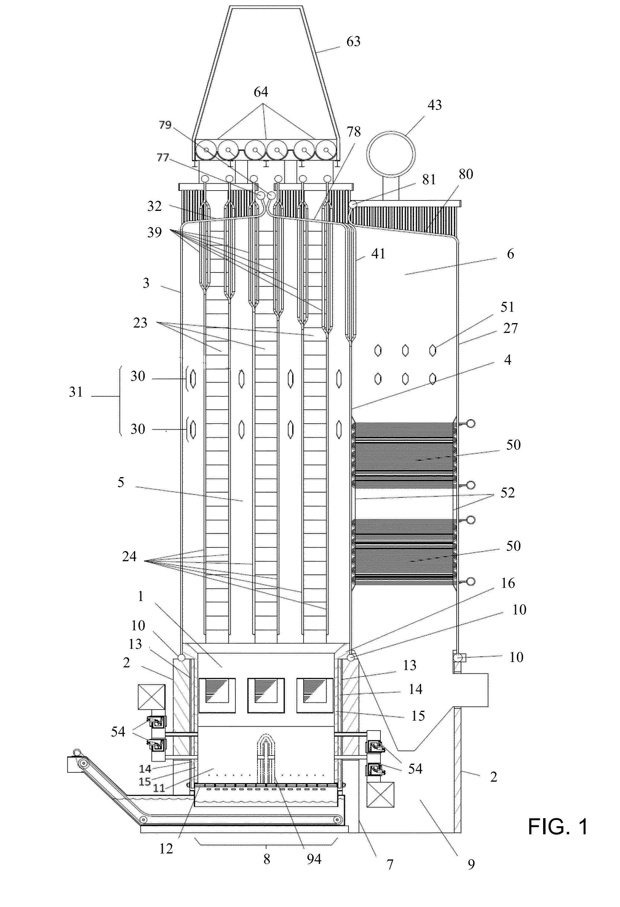
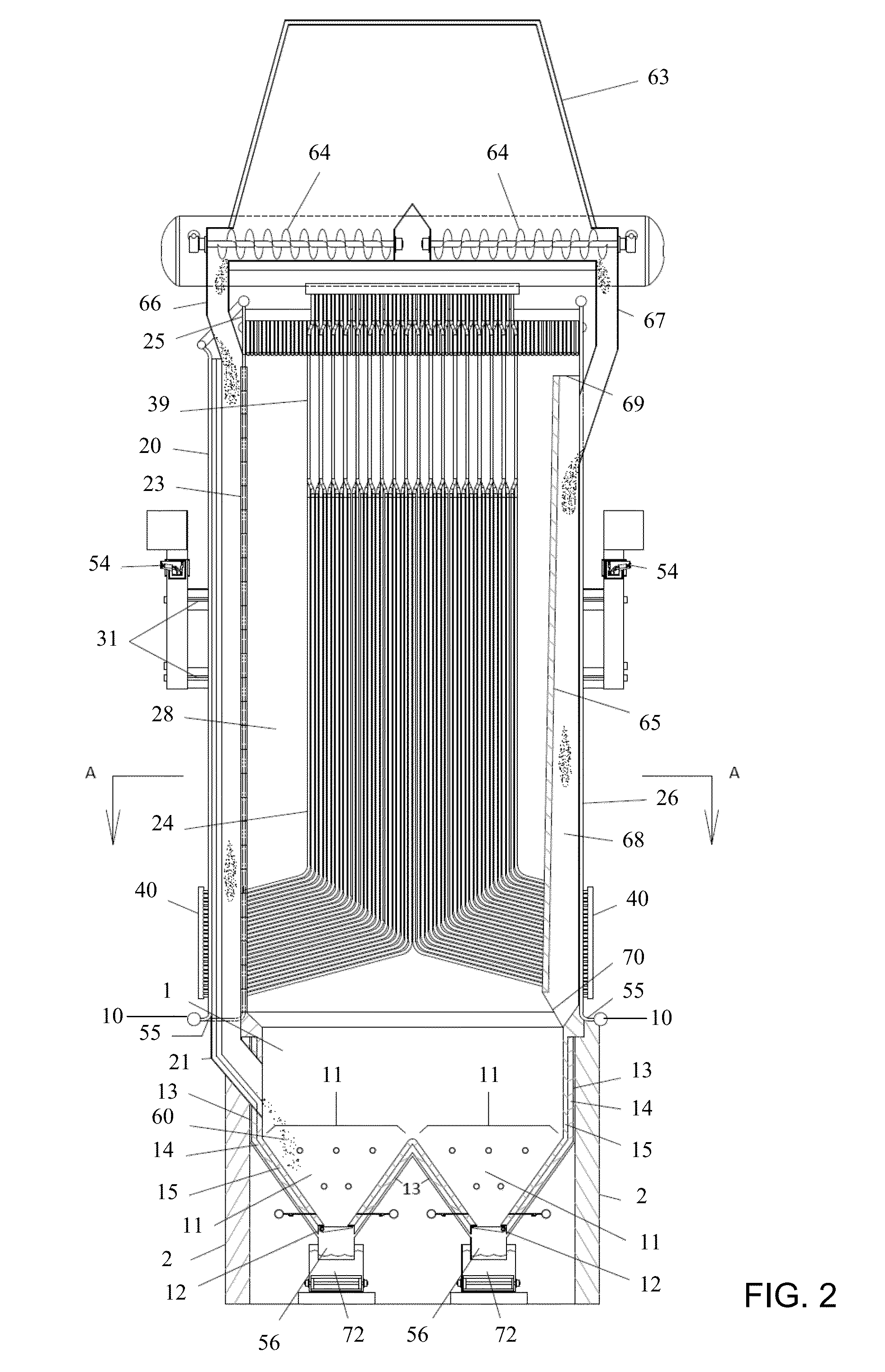
[0019]The accompanying drawings are referred to in the following description. FIG. 1 is a sectional side view of the boiler and FIG. 2 is a sectional front view. FIG. 3 is a sectional plan view cut through the boiler at Section A-A in FIG. 2 with the front of the boiler at the bottom. FIGS. 4 and 5 are enlargements of the bottom of the boiler from FIGS. 2 and 1 respectively to illustrate some of the features and operation of the boiler. The numbers in this text refer to like numbers illustrated in the drawings. Referring now to FIGS. 1 and 2, the combustion chamber 1 is surrounded by a reinforced concrete foundation 2 that rises 15 to 20 feet or more above the ground. Foundation walls 2 support front tube wall 3, left tube wall 25, right tube wall 26, and rear tube wall 27 of the boi...


PUM


Abstract

A ground supported single drum power boiler is described combining a refractory lined and insulated V-Cell floor; refractory lined and insulated combustion chamber; integrated fuel chutes configured to pre-dry wet solid fuel; top mounted fuel bin; internal chamber walls; configurable combustion air systems; and a back pass with after-burner ports and cross flow superheaters. The boiler can be configured in pre-assembled modules to minimize the field construction time and cost. An alternative embodiment is adaptable as a gasifier.

Description

[0001]This application claims priority from U.S. Prov. Pat. No. 61 / 616,211, filed Mar. 27, 2012, which is hereby incorporated by reference.BACKGROUND OF THE INVENTION[0002]Power boilers have long been used by industries and utilities to produce steam for power production and process requirements. These boilers come in many types and sizes but embodiments of the present invention are an improvement on bed-fired water tube boilers ranging in steam production from 25 tons per hour to 300 tons per hour or more. The fuel may consist of bark, sawdust, wood chips, biomass trimmings, wood or other biomass pellets, urban waste, tire derived fuel (TDF), crushed coal, pet coke, sludge, fiber line rejects, straw based fuels, or other solid fuel, or a combination of fuels, and may have moisture content as high as 60%. These boilers are typically constructed of heavy wall steel tubes welded side by side into wall panels that form the front, rear and side walls of the boiler. The lower portion of ...

Claims


Application Information

Patent Timeline
Patent Type & Authority Applications(United States)
IPC IPC(8): F22B21/00F23C9/00F23L7/00F23K3/00F22G1/04F23M3/22F23H13/06
CPCF22B21/00F23M3/22F23C9/00F23H13/06F23K3/00F23L7/007F22G1/04F23G5/002F23G5/04F23G5/46F23G7/10F23J1/00F23C2900/01001F23G2202/106F23G2205/16F23G2206/10F22B21/14F22G5/02Y02E20/34Y02E20/12F23C9/006F23G5/24F23G7/00F23G5/05
Inventor HIGGINS, DANIEL R.SULLIVAN, EUGENE
Owner SULLIVAN HIGGINS & BRION PPE LLC
Why Eureka
Try Eureka