Methods, apparatus and system to support large-scale micro- systems including embedded and distributed power supply, thermal regulation, multi-distributedsensors and electrical signal propagation

a micro-system and large-scale technology, applied in the field of integrated circuits, can solve the problems of large-scale global failure of the entire ic, inability to process an entire wafer with current deep-sub-micron lithography, and increase the size of the integrated circuit (ic), so as to improve signal integrity, enhance the operation, and increase the thermal gradient

Inactive Publication Date: 2013-10-31
TRANSFERT PLUS S E C +2
View PDF6 Cites 108 Cited by
  • Summary
  • Abstract
  • Description
  • Claims
  • Application Information

AI Technical Summary

Benefits of technology

[0102]The present invention also relates to electronics serial communication systems needing robust defect tolerant features to improve production yields.
[0233]The expression “support frame” as used herein refers to a multi-layer stack structure such that each layer can be a heatsink, PCB, ceramic, silicon PCB, thermal grease, balls, MEMS, NEMS or any material that can be used to reduce mechanical stress on fragile LAMS devices and / or to interconnect devices for power supply or data signal propagation.

Problems solved by technology

The size of an integrated circuit (IC) increases not only its cost, but also the probability that manufacturing defects appear on its surface.
Not all defects cause dramatic global failure on the entire IC.
Some defects are benign; some generates various faults such as opens, shorts, stuck-at-one, stuck-at-zero.
It is not possible with current deep-sub-micron lithography to process an entire wafer as single reticle image.
Even for mature microfabrication processes, manufacturing defects significantly reduce the yield of large functional ICs.
Defects appear randomly on a LAIC, and most of the time they cannot be detected by visual inspection, so it is impossible to know where defects are located by means other than electrical testing.
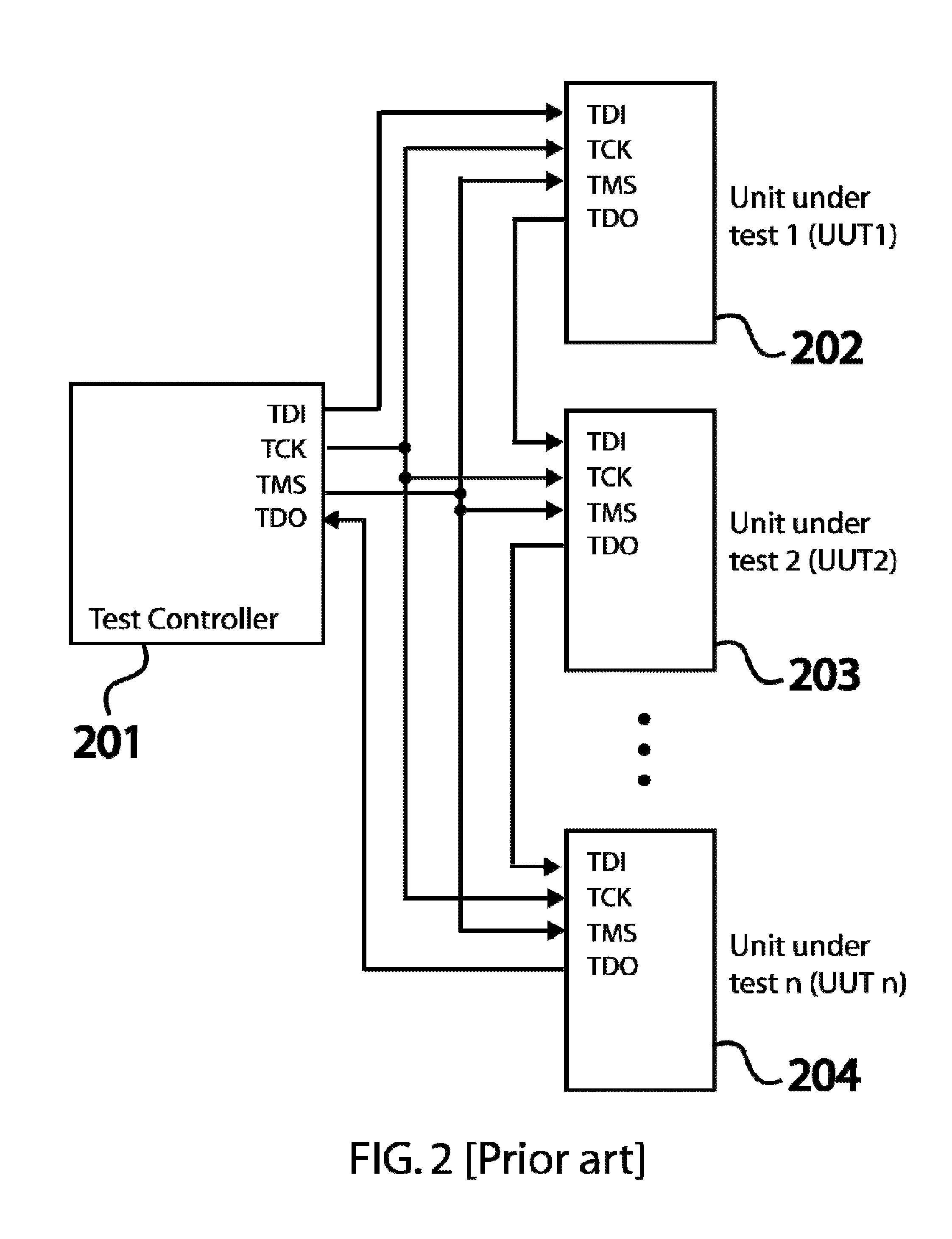
But the daisy-chained UUTs have a major vulnerability: if only one UUT in the ring is dysfunctional, the whole ring is not testable and not configurable, so the whole system becomes non-functional.
But this solution requires an addressable multi-dropout module resulting in an increase of IC's area consumption.
If the multi-dropout bus contains a single fault, the whole PCB or IC is dysfunctional.
The loss of a large and dense system due to failure of the test hardware can be very expensive and can impact its profitability.
By default, LAICs produced with advanced semiconductor manufacturing are complex systems in which multiple defects are expected with a high probability.
This is complex to implement and it usually demands redesigning logic cells using full-custom circuit layout.
The main limitations with these relatively generic prior art solutions are the test time and diagnosis resolution.
Test phase B is able to detect shorts and SA faults, but fails to locate precisely the SA fault.
It is known from previous work that the basic walking one approach is too slow to test and diagnose large networks.
Fault tolerance (or defect tolerance) becomes an unavoidable topic as the scale of ICs is decreasing toward the physical limits of the photolithographic process.
Furthermore, the increasing interest in wafer scale packaging and wafer scale integration system make defect tolerance a very important design issue to improve production yields.
Designers working on 3D chip architectures face the major problem of increased power density.
High temperatures create problems such as frequency throttling, increased noise, decreased chip life expectancy and degraded chip reliability.
Another problem created by heat appears in LAICs.
If the gradients are too large, it could result in breaking the silicon substrate and permanently damaging the system.
Stacked layers are very densely interconnected making observation of 3D interconnects very difficult.
Efficient and standardized tests of 3D stacked ICs are difficult to achieve.
Furthermore, for the same reason, it is harder to diagnose faults in 3D stacked IC for devices being prototyped and devices under validation.
But no existing system can program assertions in dedicated hardware inserted in a programmable interposer.
At-speed observability and controllability of 3D stacked chips is hard to achieve because interconnects could be buried in the core of the 3D stacked chips.
Therefore, the increased miniaturization of the 3D stacked chips makes at-speed DFT harder to achieve.
No previous system offers the possibility to observe all the digital pins of all chips in the system.
BIST is extensively used in industry, but no existing interposer offers the possibility to program a BIST for rapid prototyping of DFT in 3D stacked chips.
To diagnose problems encountered in some system under test, it is desirable to implement a BIST specialized for diagnosis; however, no existing interposer can configure an embedded BIST circuit dedicated to diagnosis of 3D stacked chips.
On the other hand, energy efficient electronic systems are becoming a strategic issue in electronics.
Furthermore, one of the most important challenges is to invest resources on research to develop new technologies that can make easier an evolution towards a more sustainable society.
However, the standard does not provide specific DPM methods to improve energy efficiency.
When workload statistical behavior is changing over the time, the accuracy of the wake-up and shut-down predictions is directly compromised.
No existing method can capture data coming from the software and from any digital pin of the system to learn from the past workload because having observability on every pin of every system component has never been done before.
The existing DPM policies are very basic due to the complexity of the problem.
DTM pro-actively reacts to predicted thermal crisis by using scheduling algorithms, but inevitably with performance degradation.
A solution to propagate a differential signal on a LAIC has already been proposed [24], however, such approach does not offer spatial reconfiguration as needed by the system.
Dissymmetry induces jitter between the two differential signals and can lead to loss of the transmitted information.
Very stringent jitter constraints exist for most high-speed interfaces.
This very short propagation time difference can be caused by slight length or load dissymmetry between paired signal paths.
Because these structures are made of materials that have different properties, specifically different coefficients of thermal expansion (CTEs), thermal stresses, distortion and warping are a source of concern.
A main reliability challenge is to ensure transient thermo-mechanical stability in LAIC systems due to the multiple embedded heat sources and the presence heterogeneous materials assembled in a multi-layer structure.
Typically, different materials will tend to have mismatches in Thermal Coefficients of Expansion (TCEs).
Heat expansion and contraction due to circuits operating can result in buckling and cracking of a LAIC system, particularly a full-wafer LAIC if attached to a rigid substrate.
Performing experiments to measure or predict the stress and temperature generated in the multilevel devices using some finite element analysis tool is costly, time consuming and device dependant.
Transient thermo-mechanical stress issues are critical for large ICs industry.
Thermal expansion and contraction due to the circuits performing normal operations can result in localized peak stress and cracking of the device, particularly in LAIC systems if they are supported or fixed to a rigid substrate or if such systems are insufficiently cooled.
These techniques, though helpful to reduce the overall power consumption, may cause significant on-chip thermal gradients and local hot spots due to different clock / power gating activities and varying voltage scaling.
An important issue with VLSI systems and micro-systems is how to perform its thermal monitoring, to detect overheating, without complicated control circuits.
While an interconnect network propagating analog signals could be implemented in parallel with a digital networks to transmit these analog signals, the capabilities of analog networks are limited (due to noise, crosstalk, delay, as well as voltage, current, and frequency range).
A dedicated parallel analog network would also be costly and very frequently left unused in predominantly digital systems.

Method used


Image

  • Methods, apparatus and system to support large-scale micro- systems including embedded and distributed power supply, thermal regulation, multi-distributedsensors and electrical signal propagation
  • Methods, apparatus and system to support large-scale micro- systems including embedded and distributed power supply, thermal regulation, multi-distributedsensors and electrical signal propagation
  • Methods, apparatus and system to support large-scale micro- systems including embedded and distributed power supply, thermal regulation, multi-distributedsensors and electrical signal propagation

Examples


Embodiment Construction

[0340]First Family of Preferred Embodiments: Software and Hardware Strategies for Defect Tolerance in Large Area Integrated Circuit

[0341]An efficient and fault tolerant scan chain for large and complex LAICs can use the generic reticle image architecture depicted in FIG. 16. Cells 608 are not necessarily identical (size, functions, circuits), and include functional modules, such as logic circuits, processors, CPUs, FPGAs, memories, DSPs, networking circuits, etc. Those cells are part of a larger system 1605 tested or configured by a TC 101. As was depicted in FIG. 1, there is one TC 101 interacting with one UUT, system 1605. Each cell has links 1603 to several neighbor cells (FIG. 16 shows the case where each cell is linked to four adjacent cells). This architecture contains two types of cell: interface cells 1604 that have direct communication links with TC and inner cells 608. The interface cell can be any cell in 1605.

[0342]Communication links can be bidirectional (as shown in FI...


PUM

PropertyMeasurementUnit
input/output impedancesaaaaaaaaaa
temperatureaaaaaaaaaa
sizeaaaaaaaaaa

Abstract

The present invention relates to technologies for integrated circuits and Large Area Integrated Circuits (LAICs), which are integrated circuits made from photo-repetition of one or several reticle image fields, stitched together on at least one lithographic process layer. It also relates to a specific class of LAIC that can connect to the contacts of other ICs placed on its surface, where specific contact detection algorithms means are disclosed. The innovations include means for defect tolerance of serial communication links, means for efficient diagnosis of short and stuck-at faults in regular reconfigurable network, means for a programmable interposer for rapid prototyping of 3D stacked chips, means to build efficient large area micro-system devices (LAMS), with distributed and configurable hierarchical structures for power supply, thermal regulation and signal propagation, means to reduce mechanical / thermal / thermo-mechanical issues in LAMS devices, means to propagate analog signal on a configurable digital network, means to predict thermo-mechanical stress peaks.

Description

[0001]The present application is a continuation of PCT / CA2011 / 050537 designating the United States, which claims the benefits of U.S. provisional application Ser. Nos. 61 / 275,722, filed on Sep. 7, 2010 and 61 / 420,766 filed on Dec. 7, 2010.STATEMENT REGARDING JOINT RESEARCH[0002]The present invention was made under joint research agreements involving École Polytechnique de Montréal, Université du Québec à Montréal and Gestion TechnoCap dated Nov. 23, 2006 and Jan. 1, 2009 and expanded to include among the parties Université du Québec en Outaouais on Nov. 29, 2007 and a Financing and Invention Agreement between Gestion TechnoCap Inc. and Richard Norman dated May 6, 2006.FIELD OF THE INVENTION[0003]The present invention relates to integrated circuits, and more particularly to integrated circuit interconnect devices and support circuits and devices for integrated circuit systems.SUMMARY OF THE PRIOR ART[0004]This section is dedicated to explain the prior works on which the present techn...

Claims


Application Information

Patent Timeline
Patent Type & Authority Applications(United States)
IPC IPC(8): H01L25/00
CPCH01L25/00H01L25/50G01R31/318555H01L23/345H01L23/36H01L23/481H01L2924/09701H01L2924/19107H01L2224/16225H01L2924/15311H01L2924/1461Y10T29/4913H01L2924/00
Inventor BLAQUIERE, YVESSAVARIA, YVONBASILE-BELLAVANCE, YANVALORGE, OLIVIERLAHKSSASSI, AHMEDANDRE, WALDERLAFLAMME MAYER, NICOLASBOUGATAYA, MOHAMEDSAWAN, MOHAMAD
Owner TRANSFERT PLUS S E C
Why Eureka
Try Eureka