Modular, Scalable High Solids Methane Digester for Small-Sized to Medium-Sized Farms

Active Publication Date: 2013-12-05
BRAGG JEFFREY H
View PDF9 Cites 4 Cited by
  • Summary
  • Abstract
  • Description
  • Claims
  • Application Information

AI Technical Summary

Benefits of technology

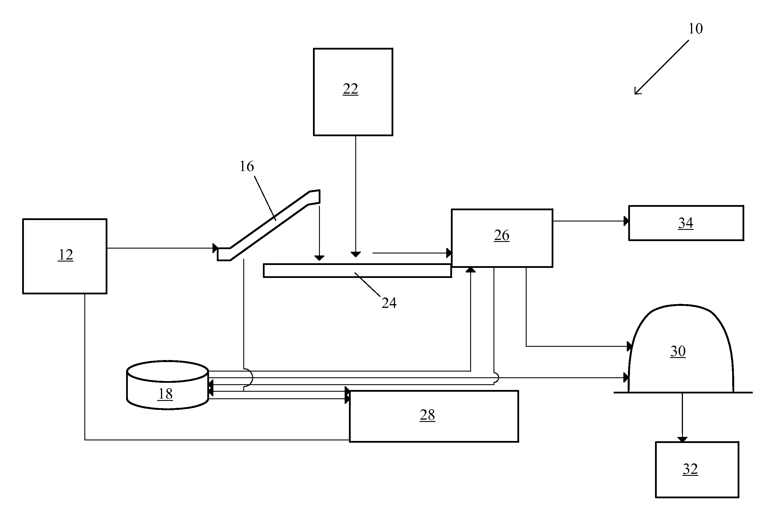
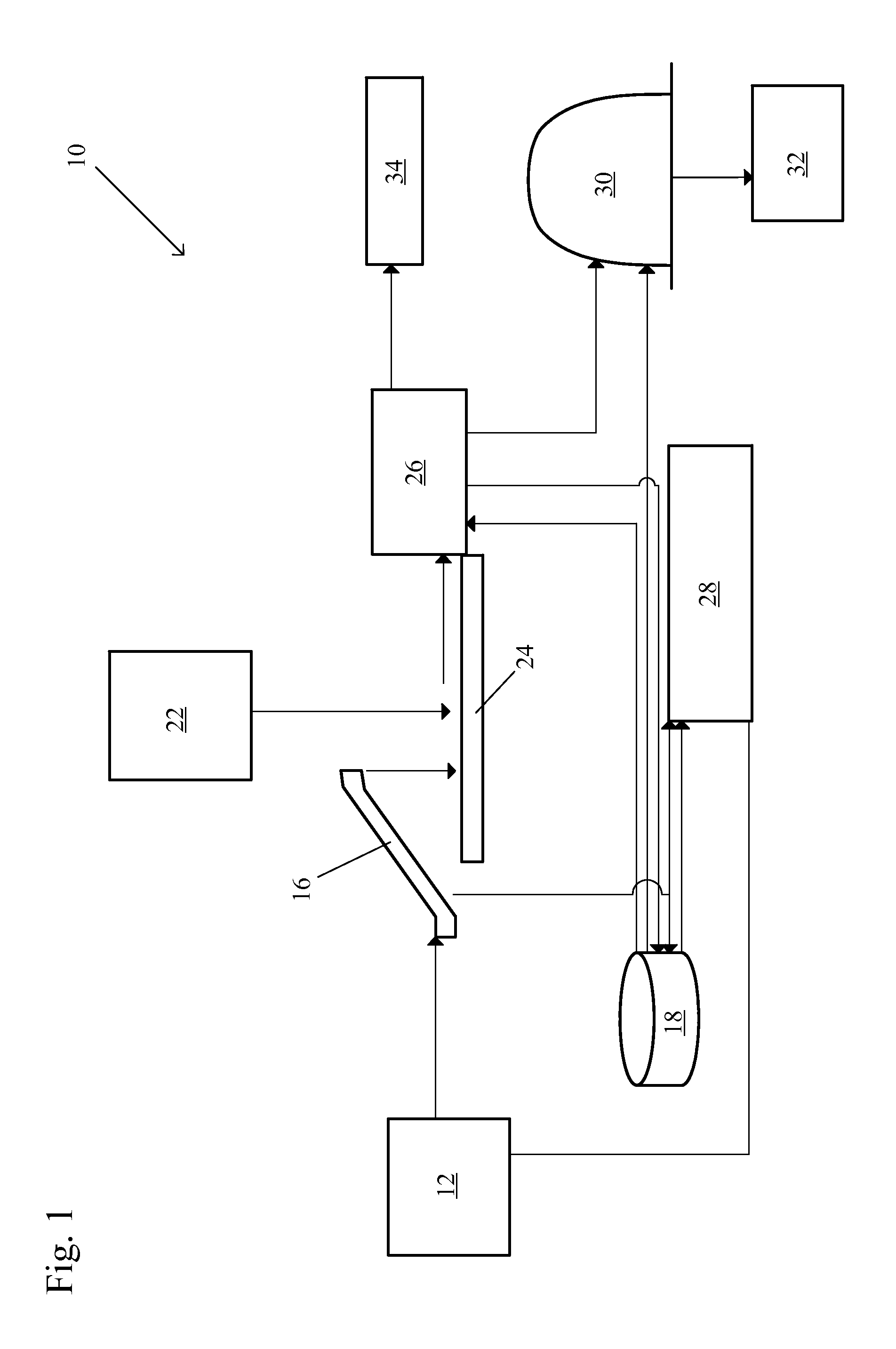
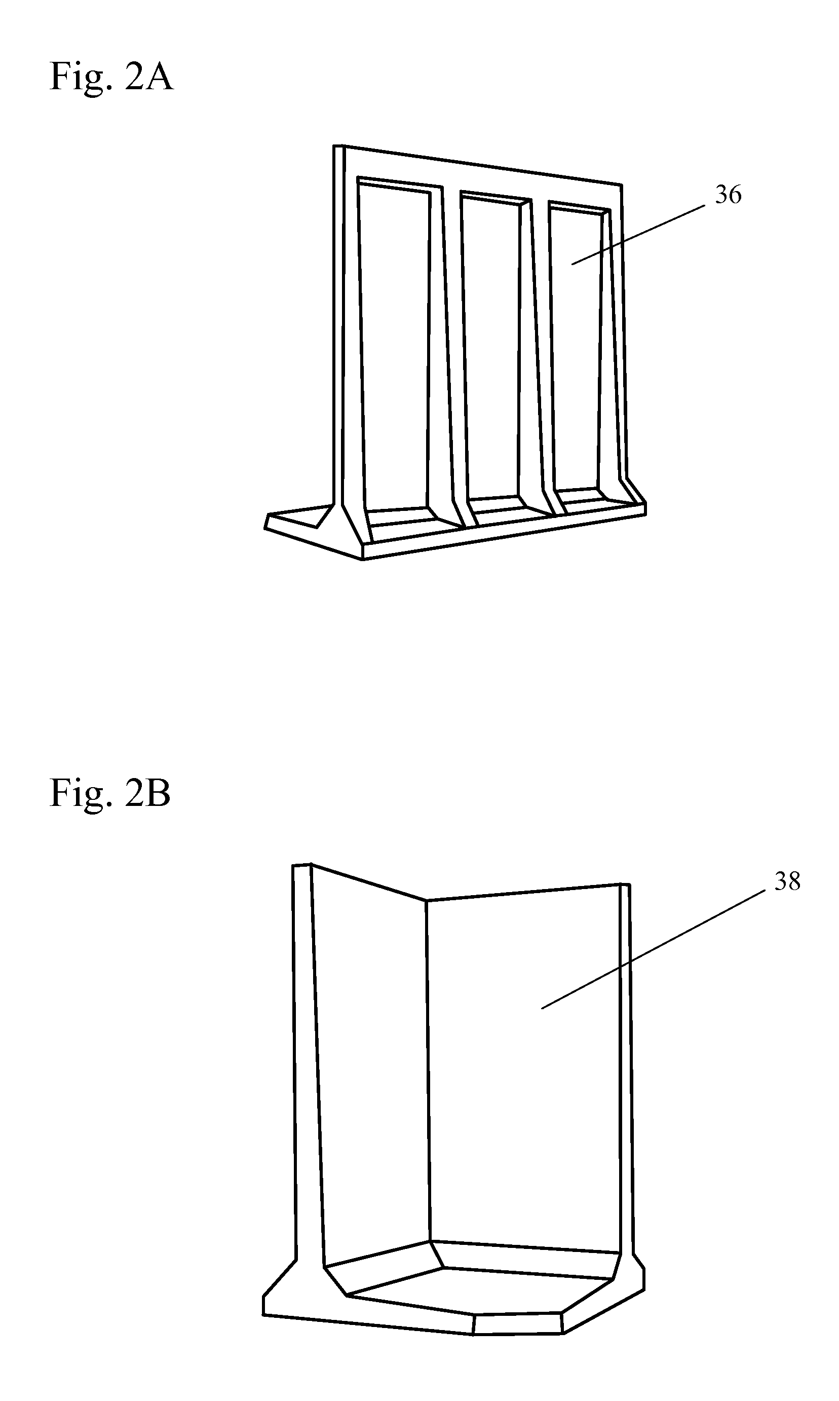
This patent describes a modular methane digester facility that uses prefabricated concrete panels and a flexible membrane roof to seal the interior space. A separator-conveyor dewatering device separates semi-solid liquid manure into a liquid and solid portion. A method of dual-stage methane digestion involves stacking a solid stage in the digester and supplying a liquid stage on top. The liquid stage percolates through the solid stage, acting as a filter and methanogenic buffer. The patent also describes a method of pre-heating a mass of solids in the methane digester to a mesophilic temperature using oxygen supplied to the digester. The technical effects of this patent include improved efficiency and control over methane production from liquid and solid manures, as well as a simplified and portable design for methane digesters.

Problems solved by technology

This may constitute a lag phase of one to several days, and if the feed stream is loaded improperly or excessively with outside ingredients, may dispose the reactor to sourness or pH crashes, recovery from which certainly meaning lost time in digestion.
An additional and significant problem with liquid-based systems, in addition to requiring massively sized tanks, is that the entire farm must essentially convert to liquid-based materials and flows and must maintain a farm disposal system for the liquid effluent resulting from the digestion process.
Effluent production is a daily phenomenon of a liquid system, and storage space for liquid effluent is limited.
Such action is not a very feasible option to farmers during the winter and summer seasons because of limited access to useable surface soil together with environmental regulatory restrictions.
Excess storage of liquid effluent, in addition to influent manure, creates the potential for overflow and entrance to surface and groundwater, particularly in inclement seasons with poor weather and above-average rainfall.
The pernicious cycle of open-air liquid systems fostering liquid restraints, sensitivity to rainfall excess that causes overloading of lagoons, and environmental damage from leaked fugitive gases and nutrient contamination of waterways from these liquids poses real constraints to the liquid-based theory of methane digestion.
Construction of large, in-ground, heated concrete tanks to handle the liquid effluents is a real cost constraint for dairy farms, and it has been proposed by many that liquid methane systems are not viable for farms with under 500 head of cattle.
It is, however, well known that methane biology is extremely scalable, meaning that the fermentation process is not, in fact, limited by size and there is no efficiency of scale pertinent to the biology.
Medium or smaller farms number in the thousands in America, yet methane digestion technologies, by the nature of focusing on a minority of large to very large dairy farms, such as 2,000 to 5,000 head operations, have thereby effectively excluded provisions for medium and small farmers of cost-effective environmental solutions to manure and waste handling, and therefore have hampered America's ability to expand energy-efficient futures.
Since the majority of the world's farms are medium to small scale, the absence of viable methane technologies for small scale approaches means that common solutions to increase viability and sustainability of farm operations from an energetic and cost-effective point of view are lacking.
While many very small farms in third-world regions have addressed the situation by design and construction of small to very small digester systems run almost entirely by manual farm hand labor, small farms in industrialized nations do not have such hand labor available and have not chosen to build these very flexible, small-scale systems.
Most of the commercial industrial engineering firms that design and construct farm methane digesters are trapped in this costly and somewhat environmentally unfriendly struggle to handle on-farm liquid wastes and provision of electricity and heat energy to large and super-sized farms, where undoubtedly the biogas solution is better than no action at all.
It does not solve the liquid handling problems and it entails huge capital reserves and debt to cover costs.
Additionally, in many regions the concept of public purchase of excess electricity generated by these large 100-500 kW systems is not sufficiently developed other than an offer of net metering to farm owned facilities or recapture by utility companies at grossly devalued worth, meaning the energy creation from methane is not a very viable path.
The efficiency of gas-to-electricity conversion, being as low as 35%, and the cost-effectiveness of such electricity generation in view of sometimes poor returns on sold or net-metered electricity, in addition to requiring a significant capital investment in energy generation units, also restricts the usefulness of the electricity approach.
The liability for over-sized, over-designed farm energy production operations falls almost entirely on the farmers themselves, as engineers and investors rarely assume management positions in on-farm systems, and failure therefore is the sole risk of the farmers as well, this coming at a time when on-farm debt has grown disproportionately to farm sustainability.
This is very costly to society as a whole, since failure of farms inevitably drives up costs of food and results in more environmental destruction from larger and super-sized farming operations.

Method used


Image

  • Modular, Scalable High Solids Methane Digester for Small-Sized to Medium-Sized Farms
  • Modular, Scalable High Solids Methane Digester for Small-Sized to Medium-Sized Farms
  • Modular, Scalable High Solids Methane Digester for Small-Sized to Medium-Sized Farms

Examples


Embodiment Construction

[0027]The integrated modular expandable design approach to methane production is space-efficient, and therefore very cost-effective, and is highly suited to small-to-medium sized farms that have hitherto been overlooked for methane digesters.

[0028]In some embodiments, methods permit the modular construction of small-to-medium scale on-farm methane digesters that are expandable and inexpensive in comparison to conventional methane digesters.

[0029]In some embodiments, the modular construction of a small-to-medium scale on-farm digester is expandable and inexpensive in comparison to conventional methane digesters.

[0030]In some embodiments, construction complexity of on-farm digesters is reduced, making it feasible for farmer-only construction of the holding tanks, or bunkers, and the associated buildings.

[0031]The methane digester preferably incorporates prefabricated concrete panels as typically employed by farmers for silage bunker walls, thereby making it modular, flexible, and expa...


PUM


Abstract

A modular methane digester facility includes prefabricated portable concrete panels and a flexible membrane roof sealing an interior space of the methane digester. A separator-conveyor dewatering device, integratable into the front end of the methane digester facility, separates a semi-solid liquid manure into a liquid portion and a solid portion. A method of dual-stage methane digestion includes stacking a solid stage in a methane digester and supplying a liquid stage to the top of the solid stage. The liquid stage percolates by gravity through the solid stage, the solid stage acts as a filter for the liquid stage, and the liquid stage acts as a methanogenic buffer for the solid stage. A method of pre-heating a mass of solids in a methane digester to a mesophilic temperature includes supplying oxygen to the mass of solids in the form of ambient air supplied to the methane digester by a reverse-air pump.

Description

BACKGROUND OF THE INVENTION[0001]1. Field of the Invention[0002]The invention pertains to the fields of agriculture and energy production. More particularly, the invention pertains to systems, methods, and structures for the production of biogas for heat and energy recovery from on-farm animal and plant residues.[0003]2. Description of Related Art[0004]Biogas production is a common feature on many farms worldwide, whereby the methane content is employed as the source of combustible energy. Farmers may customarily produce methane by exclusion of air inside sealed containers to produce a mixture of fermented gaseous byproducts as biogas. It has become very common to construct liquid-based manure systems in which outflow of daily farming operations, including manure wash and barn milk parlor, washes together with miscellaneous farm residues such as hay, straw and spent silage and feed. These mixtures are pushed or gravity-fed into cement in-ground tanks, in which, by applying elevated ...

Claims


Application Information

Patent Timeline
IPC IPC(8): C02F11/12E04B1/38E04B1/00C02F11/02E04B1/66C02F11/121C02F103/20
CPCC02F1/001C02F11/121C02F2103/20C02F2201/007C12M21/04C12M23/36C12M23/44C12M29/02C12M45/04C02F11/04C12M23/00Y02E50/30Y02W10/20
Inventor BRINTON, JR., WILLIAM F.BRAGG, JEFFREY H.
Owner BRAGG JEFFREY H
Why Eureka
Try Eureka