Fiber-based filter with nanonet layer and preparation method thereof

a fiber-based filter and nano-net technology, applied in gravity filters, separation processes, filtration separation, etc., can solve the problems of reducing flux, reducing permeation rate, and increasing the loss of pressure caused by small pores, and achieve excellent heat resistance and mechanical properties, excellent filtration efficiency, and high flux

Inactive Publication Date: 2014-03-20
KOREA INST OF SCI & TECH
View PDF7 Cites 27 Cited by
  • Summary
  • Abstract
  • Description
  • Claims
  • Application Information

AI Technical Summary

Benefits of technology

[0014]An exemplary embodiment may provide an ultra-fine fiber-based filter that has excellent filtration efficiency capable of removing even ultra-fine particles such as a virus and shows a high flux due to low loss of pressure during the filtration by introducing a nanonet layer made of an anisotropic nanomaterial into an ultra-fine fiber-based porous body to form a filtration layer.
[0017]An exemplary embodiment may provide an ultra-fine fiber-based filter that is capable of removing even ultra-fine particles such as virus and shows excellent filtration efficiency and high flux by introducing a nanonet layer made of an anisotropic nanomaterial into an ultra-fine fiber-based porous body to form a filtration layer, and a preparation method thereof.
[0021]A filter according to an exemplary embodiment may have excellent heat resistance and mechanical properties, and may show high flux while simultaneously having excellent filtration efficiency capable of removing a virus in water and air and low loss of pressure during the filtration, and thus may be used usefully as an air and water treatment filter.

Problems solved by technology

However, when a general membrane filter is used to remove ultra-fine particles such as virus and the like, the loss of pressure caused by small pores is increased to a very high level, the flux is decreased due to low permeability, and pores of the film may be blocked during the use thereof to sharply decrease the permeation rate.
Further, a general membrane filter requires frequent backwashing, and thus is limited by various temperature applications during the removal of impurities, energy consumption is high, and a material for the separation filter itself is not strong, thereby destroying the separation filter or increasing the size of pores.
Meanwhile, a fiber filter in the related art has low filtration precision and may not remove virus and the like in water, and thus, it is difficult to use the fiber filter in the water treatment precision filtration.
For example, in the case of a melt-blown non-woven fabric which is currently and universally applied to filters, the diameter of a constituent fiber is so large that nano-sized particles such as virus and the like may not be filtered.
Further, even when a polymer blend fiber is prepared by a melt-blown method and sea components are removed to prepare a super-micro fiber having a diameter distribution from 5 nm to 500 nm, a fiber having a large diameter is intermixed to form large pores, and thus filtration precision is decreased and it is difficult to remove the virus and the like in water.
When a pore size of the filtration layer is extremely small, ultra-fine particles such as a virus may be filtered with high efficiency, but it is difficult to prepare a filter having a pore size as small as the size.
That is, the pore size depends greatly on the diameter of a nanofiber and the porosity, and thus it is difficult to prepare a nanofiber having a diameter which is small enough to filter ultra-fine particles such as virus and the like.
Further, a filtration layer having the ultra-fine pores has very high filtration efficiency, but the pore size thereof is so small that high operating pressure may be required, the loss of pressure may be too great, and the flux may be too low.
Accordingly, the filtration efficiency is increased, but the permeation capacity is reduced to a very low level, and thus it may be difficult to simultaneously satisfy high filtration efficiency and high flux.
However, the drawback of the sol-gel method is that irregular particles are formed and thus it is extremely difficult to control the pore size.
Further, during the drying process by the sol-gel method, pinholes and cracks are generated, the length of pores is increased, thereby decreasing the flux, and low porosity and the presence of dead end pores may make it difficult to prepare a ceramic filter having high selectivity and high flux.
In addition, a filter only using a ceramic super-micro fiber has brittle characteristics of a ceramic material as it has, and thus, mechanical properties of the filter may be weak and when the thickness of the filter is increased in order to overcome the problem, the flux may be sharply decreased.

Method used


Image

  • Fiber-based filter with nanonet layer and preparation method thereof
  • Fiber-based filter with nanonet layer and preparation method thereof
  • Fiber-based filter with nanonet layer and preparation method thereof

Examples


example 1-1

Preparation of Bohemite Nanofiber

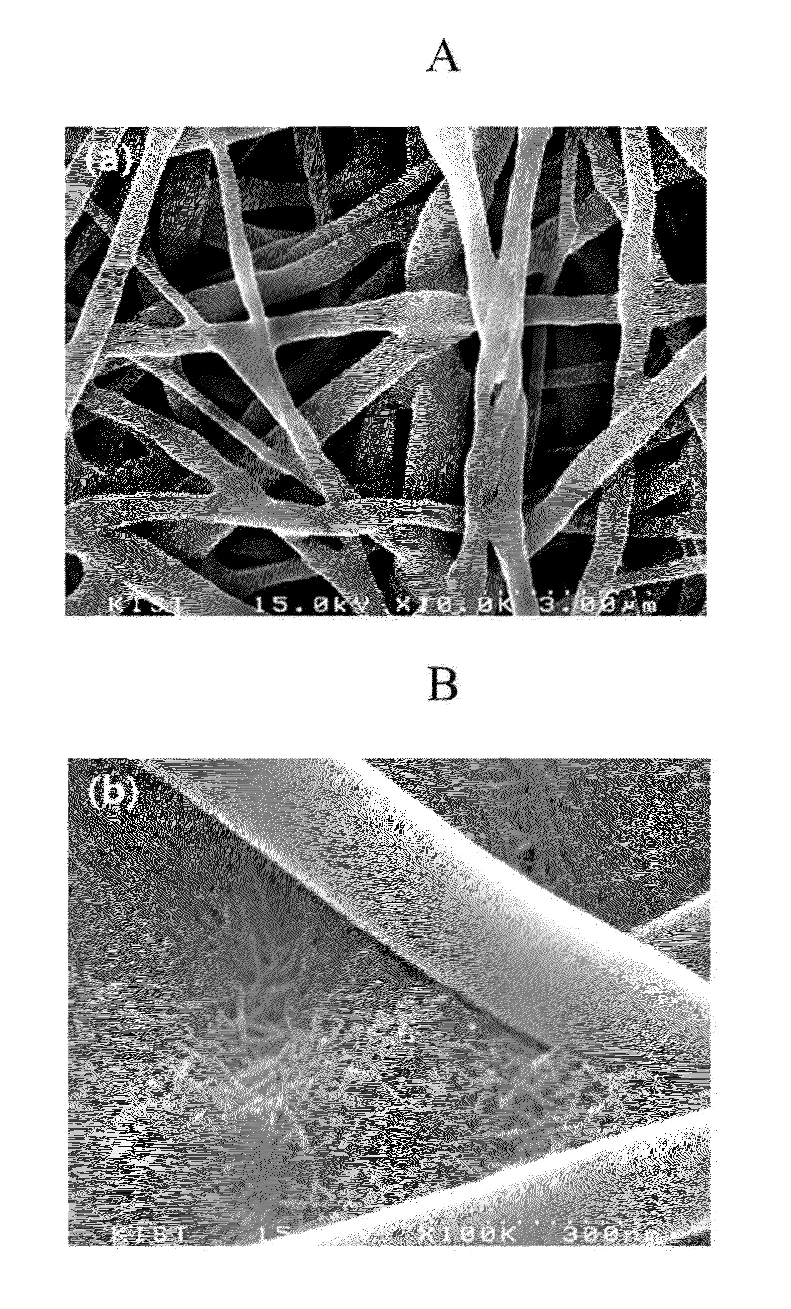
[0085]About 15 mL of aluminum butoxide [Al(O-secButyl)3] was put into about 1,450 mL of distilled water, and about 10.9 mL of hydrochloric acid was added thereto to prepare a white dispersion liquid. About 38 g of aluminum isopropoxide [Al(O-isoPropyl)3] was added to the white dispersion liquid, and then the mixture was ultrasonically stirred in an ice bath for about 1 hour. FIG. 3 is a scanning electron microscope (SEM) photo illustrating the surface of a bohemite nanofiber porous layer composed of a nanonet structure obtained by filtering the dispersion liquid.

[0086]FIG. 3 is a scanning electron microscope (SEM) photo illustrating the surface of a bohemite nanofiber porous layer composed of a nanonet structure obtained by filtering the dispersion liquid. Referring to FIG. 3, a bohemite nanonet layer may be introduced into the filter when dispersion liquid is used.

example 1-2

Preparation of Bohemite / Carbon Nanotube Complex

[0087]About 15 mL of aluminum butoxide [Al(O-secButyl)3] was put into about 1,450 mL of distilled water, and about 10.9 mL of hydrochloric acid was added thereto to prepare a white dispersion liquid. About 38 g of aluminum isopropoxide [Al(O-isoPropyl)3] and multi-wall carbon nanotube (MWCNT, supplied by Nanocyl Inc.) were added to the white dispersion liquid, and then the mixture was ultrasonically stirred in an ice bath for about 1 hour. The stirred solution was reacted at about 150° C. in a high pressure reactor connected with a Teflon tube for about 22 hours and 22 hours, and then white dispersion liquids as shown in FIG. 4 were prepared.

[0088]FIG. 4a illustrates a dispersion liquid of a bohemite / carbon nanotube complex obtained after reaction for about 12 hours and a transmission electron microscope (TEM) photo thereof. Referring to FIG. 4a, an aspect that bohemite is adsorbed on the surface of carbon nanotube is shown. FIG. 4b is ...

example 2-1

Electrospray of Dispersion Liquid of Bohemite Nanofiber to SiO2 / PVdF Complex Ultra-Fine Fiber-Based Porous Body

[0089]The dispersion liquid of bohemite nanofiber prepared in Example 1-1 was sprayed on the SiO2 / PVdF ultra-fine composite fiber-based porous body prepared in Comparative Example 2 [FIG. 5a] through a spinning nozzle of about 27 G under a high-voltage electric field of 12 kV at a discharge rate of about 30 μl / min.

[0090]FIG. 5b illustrates a nanonet structure composed of a bohemite nanofiber formed on the surface of a fiber-based porous body.


PUM

PropertyMeasurementUnit
pore size distributionaaaaaaaaaa
lengthaaaaaaaaaa

Abstract

A fiber-based filter includes a filter-based porous body having a most frequent pore size from 0.1 μm to 2 μm in a pore size distribution, in which a ultra-fine fiber is continuously and randomly disposed, and a filtration layer having a nanonet layer having a most frequent pore size from 1 nm to 100 nm in the pore size distribution, in which an anisotropic nanomaterial is disposed. The fiber-based filter may have excellent filtration efficiency capable of removing even super-fine particles such as virus and heavy metal, and may show high permeation flow rate due to low loss of pressure during the filtration, and may be usefully used as an air and water-treatment filter.

Description

CROSS-REFERENCE TO RELATED APPLICATION[0001]This application claims priority to and the benefit of Korean Patent Application No. 10-2012-0104542 filed in the Korean Intellectual Property Office on Sep. 20, 2012, the entire contents of which are incorporated herein by reference.BACKGROUND OF THE INVENTION[0002](a) Field of the Invention[0003]A fiber-based filter with a nanonet layer and a preparation method thereof are provided.[0004](b) Description of the Related Art[0005]In a water purification system, a membrane filter that separates fine particles by a film having pores smaller than particles to be filtered is generally used, and examples of the membrane filter include microfiltration (MF; pore size 50 nm to 2,000 nm), ultrafiltration (UF; pore size 1 nm to 200 nm), reverse osmosis (RO; pore size 0.1 nm to 2 nm) used in desalination, and the like. Such a membrane-based liquid filter and separation technology are useful in the water treatment field such as oil / water emulsion separ...

Claims


Application Information

Patent Timeline
Patent Type & Authority Applications(United States)
IPC IPC(8): B01D39/16
CPCB01D39/1623B01D39/2041B01D2239/025B01D2239/065B01D39/14B01D69/06B01D69/12B01D71/00
Inventor JO, SEONG-MUKIM, DONG-YOUNG
Owner KOREA INST OF SCI & TECH
Why Eureka
Try Eureka