
Dual-Zone, Atmospheric-Pressure Plasma Reactor for Materials Processing

Inactive Publication Date: 2014-06-26
SELWYN GARY S
View PDF16 Cites 14 Cited by
  • Summary
  • Abstract
  • Description
  • Claims
  • Application Information

AI Technical Summary

Benefits of technology

This patent describes a plasma treatment process that has several technical benefits. Firstly, the substrate is treated in two different plasma zones, which reduces the risk of damage to the substrate and allows for faster treatment rates. Secondly, the process uses a single, large diameter tube for the rf electrode, which simplifies the design and operation. The patent also mentions the option to add a perforated, passive secondary electrode to create a low-density plasma generation region and help transport plasma-generated active species to the substrate with reduced loss or recombination. Overall, this plasma treatment process offers more efficient and effective materials processing than previous methods.

Problems solved by technology

The challenge is that atmospheric pressure plasma technology is generally less-developed than vacuum-based plasma technology.
These active, chemical species typically exist in a short-lived excited state, which cannot otherwise be stored or easily formed.
Typically, this results because the excited state metastable is in a different spin state than the ground state species and so cannot release its stored energy by the simple emission of light.
However, direct exposure of the workpiece to the plasma generation region can have undesirable effects, such as promoting the out-gassing of contaminants from the workpiece, including water vapor, monomer vapor and other volatile chemicals from the workpiece.
Release of these undesired species may interfere with the intended chemical reaction(s) and the contaminant species may also cause the plasma to arc.
The difficulty in downstream plasma processing is the need to transport the active chemical species to the substrate before they extinguish due to recombination and other surface and gas-phase reactions.
Because of this, downstream processing can be expensive, especially when expensive noble gases such as helium are used to generate the plasma and to increase the linear velocity of the gas flow.
In summary, in-situ processing reduces the gas flow required for materials treatment, but introduces problems with plasma-initiated out-gassing and creates a susceptibility to arcing and consequent substrate damage, whereas downstream processing minimizes arcing issues and out-gassing, but requires a high gas flow for efficient treatment, which can be expensive.
For in-situ plasma treatment processes, high power plasmas increase processing speed, but can also create increased vulnerability to arcing and substrate damage, as well as undesired chemical reactions from the increased substrate out-gassing.
Even subtle changes in the thickness of the substrate caused by folds, seams or weave defects can result in arcing for a high power, in-situ process.
For downstream processes, higher power plasmas offer only increasing benefits with no significant negative results, but there remains the problem of transporting the active species to the substrate surface.
The need to have a high power atmospheric pressure plasma source that also operates with a low gas temperature (i.e., <75 C) introduces yet another issue, since the ultimate result of adding energy into a gas is an increase in its kinetic energy, and therefore its temperature.
The result is that a very high instantaneous plasma density is achieved; however it is with a relatively low duty cycle and has low average plasma density.
The use of a dielectric cover on the electrode still acts as a barrier for heat removal because dielectric materials are generally poor heat conductors.
Because of this, all atmospheric pressure plasmas having a dielectric cover on the electrodes will have difficulty removing heat from the plasma, even if the electrodes are water-cooled.
In these, the use of helium as a plasma gas will improve the thermal conductivity of the plasma, but the limiting factor for heat removal remains the poor thermal conductivity of the dielectric cover.
These plasmas are also limited in average plasma density due to the presence of the dielectric cover and the impedance to current flow caused by the dielectric cover.
However, since a screen electrode cannot be water-cooled to aid in heat removal, the gas flow can be hot.
At atmospheric pressure, the high concentration of M makes this reaction fast, resulting in a short lifetime, or short transit distance, of the atomic oxygen.
This means that either a high helium flow rate is needed or the transit distance to the substrate must be very short.
The limiting factor for high power plasma generation becomes the design capability for holding the ground electrode tubes perfectly straight: variations in the gap between ground electrode tubes and the planar, rf electrode will cause the plasma density to be highest wherever the gap dimension is shortest because the electric field will be greatest at these points.
The difficulty in using this invention is that the ground electrode tubes must be held perfectly straight, which is hard to do for a long section, such as 72″ width.
Thus, in practice, large units of this design are prone to arcing issues if not properly manufactured.
In addition, the need to efficiently water-cool the full length of the tubes (which is promoted by large diameter tubing) and the need to minimize the transit time of the active species from the plasma to the workpiece (which is promoted by small diameter tubing), are in conflict.
If the water flow is not equal through each of the tubes, or if the water flow is not sufficient to handle the power of the plasma, heating of the tubes by thermal exchange with the plasma will result in expansion and deformation, which may lead to arcing as the electrode gap is changed.
Finally, contaminants, such as water vapor or monomer vapor that flow into, or are reflected into, the plasma volume, can cause arcing.
This can happen if the gas flow that is compressed between the ground electrode tubes is not uniform or is not sufficient to prevent back-flow of gases due to gas reflection from the workpiece.
Even trace contaminants inside the plasma can cause arcing if they change the plasma chemistry.
In-situ treatment of thick substrates, meaning more than 3-4 mm, remains problematic using the approach of US2006 / 0048893 and other in-situ, non-DBD plasmas.
As is apparent from the foregoing, in-situ processing offers the potential benefit of rapid substrate treatment due to the high density of active, chemical species that can be achieved, but suffers from problems of arcing, especially for high power plasmas.
In addition, it is difficult to apply in-situ processing methods to thicker substrates.
Downstream plasma processing offers a solution to the arcing problem and can treat thicker substrates, but is expensive due to the need for high gas flow rates to transport the active species and / or long exposure times. Therefore there is a desire to provide an improved plasma treatment process and apparatus that combines the advantages of the downstream plasma with the advantages of an in-situ plasma.

Method used


Image

  • Dual-Zone, Atmospheric-Pressure Plasma Reactor for Materials Processing
  • Dual-Zone, Atmospheric-Pressure Plasma Reactor for Materials Processing
  • Dual-Zone, Atmospheric-Pressure Plasma Reactor for Materials Processing

Examples


Embodiment Construction

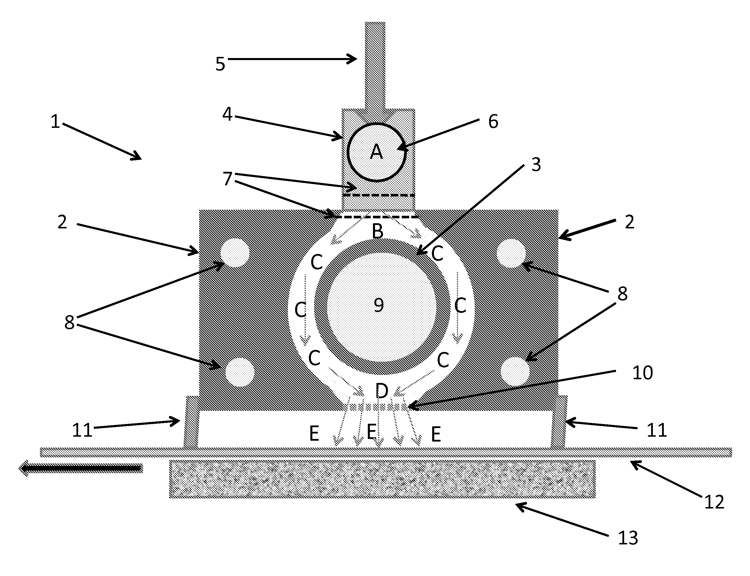
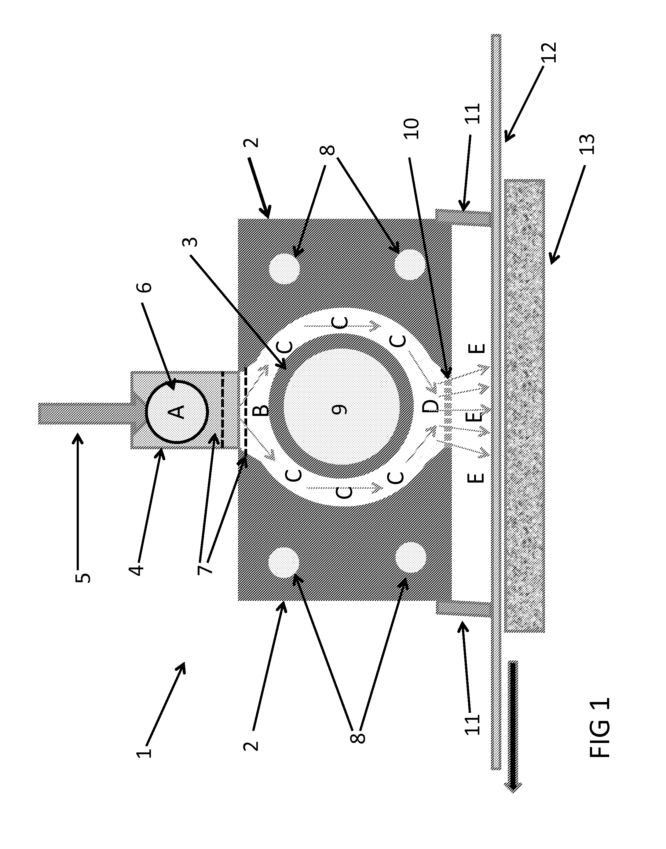
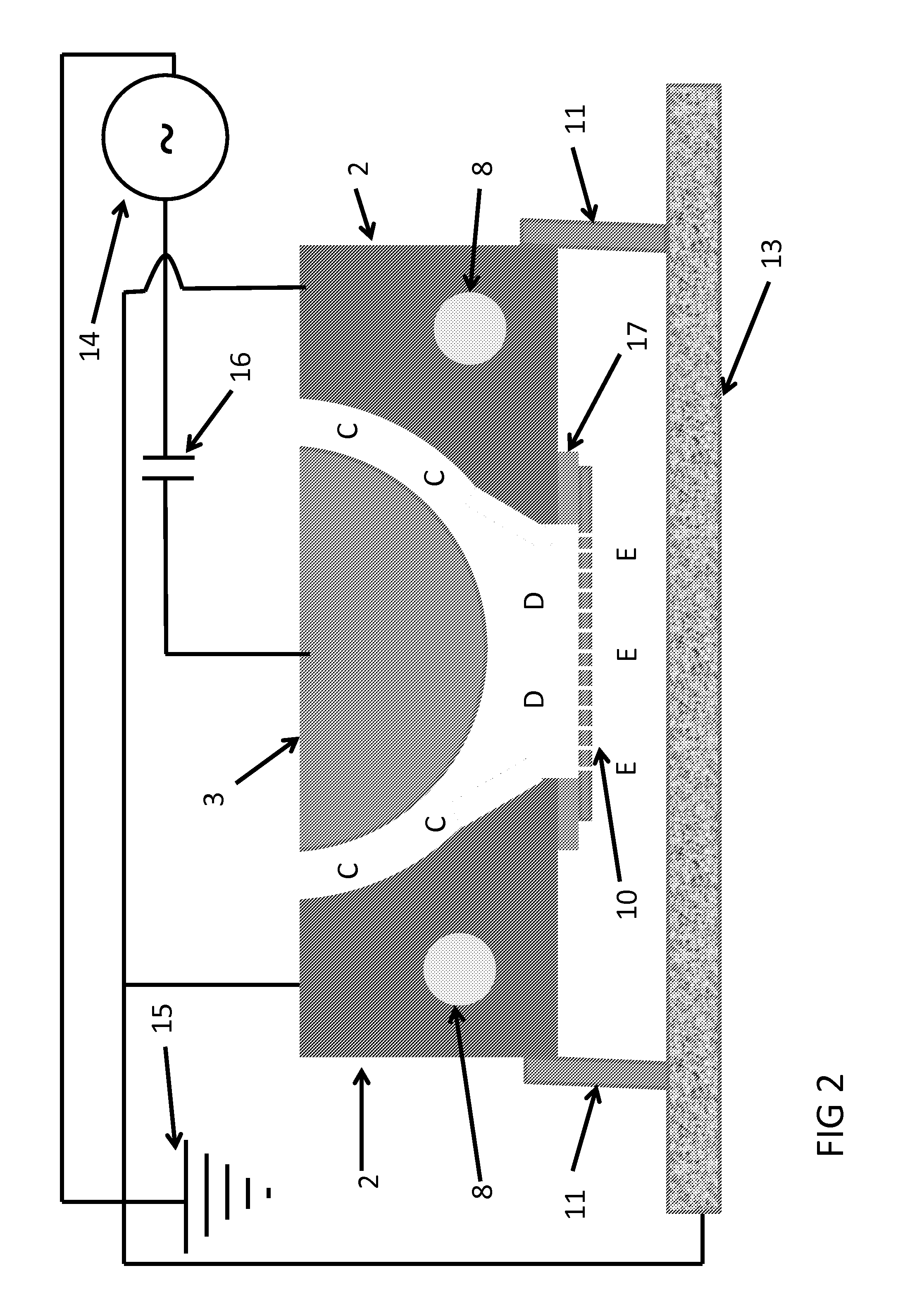
[0055]Turning now to FIG. 1, the preferred embodiment of the present invention, apparatus, 1, is shown with gas flow regions denoted by A, B, C, D, and E. Ground electrode 2, which in the embodiment shown consists of 2 parts, each located equidistant from and on either side of radio-frequency electrode 3, which as shown (and as preferred) is water-cooled through center 9. RF electrode 3 is shown as a tubular electrode, but could also be a planar electrode with an internal water cooling channel, in which case ground electrode 2 would be one or planar electrodes spaced equidistant from electrode 3, as shown in FIG. 5. Ground electrode 2 may consist of one or more parts to simplify. As shown, ground electrode 2 includes water cooling channels 8, which may be circular, rectangular, square or some other shape. Ground electrode 2 may be made by attaching two or more sections which have a channel machined into each section to fit a cooling tube or tubes that carry chilled water. Cooling ch...


PUM

PropertyMeasurementUnit
Temperatureaaaaaaaaaa
Fractionaaaaaaaaaa
Distanceaaaaaaaaaa

Abstract

A substrate is treated with a plasma by passing a gas through a first strong electrical field to form a plasma having active species and ionized species, passing at least a portion of said active species and ionized species into a second, weaker electrical field to generate a second but weaker plasma generation zone. Active species formed in said first plasma or said second plasma impinge onto the substrate to perform the desired treatment. The process allows a greater concentration of active species to reach the substrate than can be formed by the second plasma alone, while reducing arcing, maintaining a low gas temperature and providing other benefits.

Description

BACKGROUND OF THE INVENTION[0001]The present invention relates to atmospheric pressure plasma reactors and methods for treating a substrate with an atmospheric pressure plasma.[0002]Plasmas are used for a wide variety of material processing applications. Both vacuum-based plasma and atmospheric-pressure plasma have been successfully employed for such applications. Many material processing applications can be carried out more easily at atmospheric pressure because this approach removes the requirement that the workpiece must be vacuum-compatible and does not contain a significant amount of volatile content that may outgas and thereby contaminate the vacuum or the process. In general, the cost of using an atmospheric pressure plasma treatment should be lower than vacuum-based plasma methods because there is no need for the apparatus to generate and maintain a vacuum. This is especially true for roll goods, such as textiles, nonwovens, paper and plastic films, which must be continuousl...

Claims


Application Information

Patent Timeline
IPC IPC(8): H01J37/32
CPCH01J37/32422H01J37/32449H01J37/32357H01J37/32568H01J37/32825H01J37/32541
Inventor SELWYN, GARY S.
Owner SELWYN GARY S
Learn More