Polymer solar cell and method for preparing same

a solar cell and polymer technology, applied in the field of solar cells, can solve the problems of affecting the service life of the device, low open circuit voltage and photoelectric conversion efficiency of solar cells, etc., and achieve the effects of simple doping process, stable, and inexpensiv

Inactive Publication Date: 2014-09-11
OCEANS KING LIGHTING SCI&TECH CO LTD
View PDF0 Cites 1 Cited by
  • Summary
  • Abstract
  • Description
  • Claims
  • Application Information

AI Technical Summary

Benefits of technology

[0006]Accordingly to this, the present disclosure is directed to provide a polymer solar cell with a better corrosion resistance and a method for preparing the polymer with a better corrosion resistance.
[0024]In the polymer solar cell, the lithium compound with less electrons is doped into the metal compound host as a dopant guest, which helps to form a p-type doped layer conducive to the hole transport. The dopant guest and the metal compound host are stable, inexpensive, have a simple doping process, its raw materials are readily available, and do not corrode the anode conductive substrate, which is conducive to the industrial production. Furthermore, the doping of the p-type doped layer is conducive to the hole transport, thus the hole transmission rate is increased. Further still, the collection hole rate of the anode conductive substrate is improved, thereby improving the energy conversion efficiency of the polymer solar cell.

Problems solved by technology

These solar cells had problems of very low open circuit voltage and photoelectric conversion efficiency.
When the aqueous mixture is spin-coated on the anode substrate, since the aqueous mixture is acidic, ITO will be corroded, thereby affecting the service life of the device.

Method used


Image

  • Polymer solar cell and method for preparing same
  • Polymer solar cell and method for preparing same
  • Polymer solar cell and method for preparing same

Examples


example 1

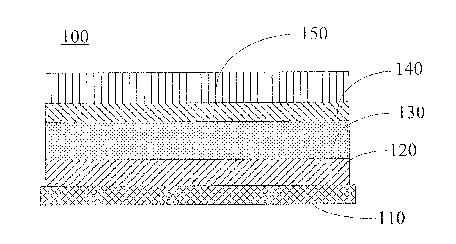
[0051]The polymer solar cell has a structure of ITO / ZnO:Li2CO3 / P3HT: PCBM / LiF / Al.

[0052]The preparation process is described as follows:

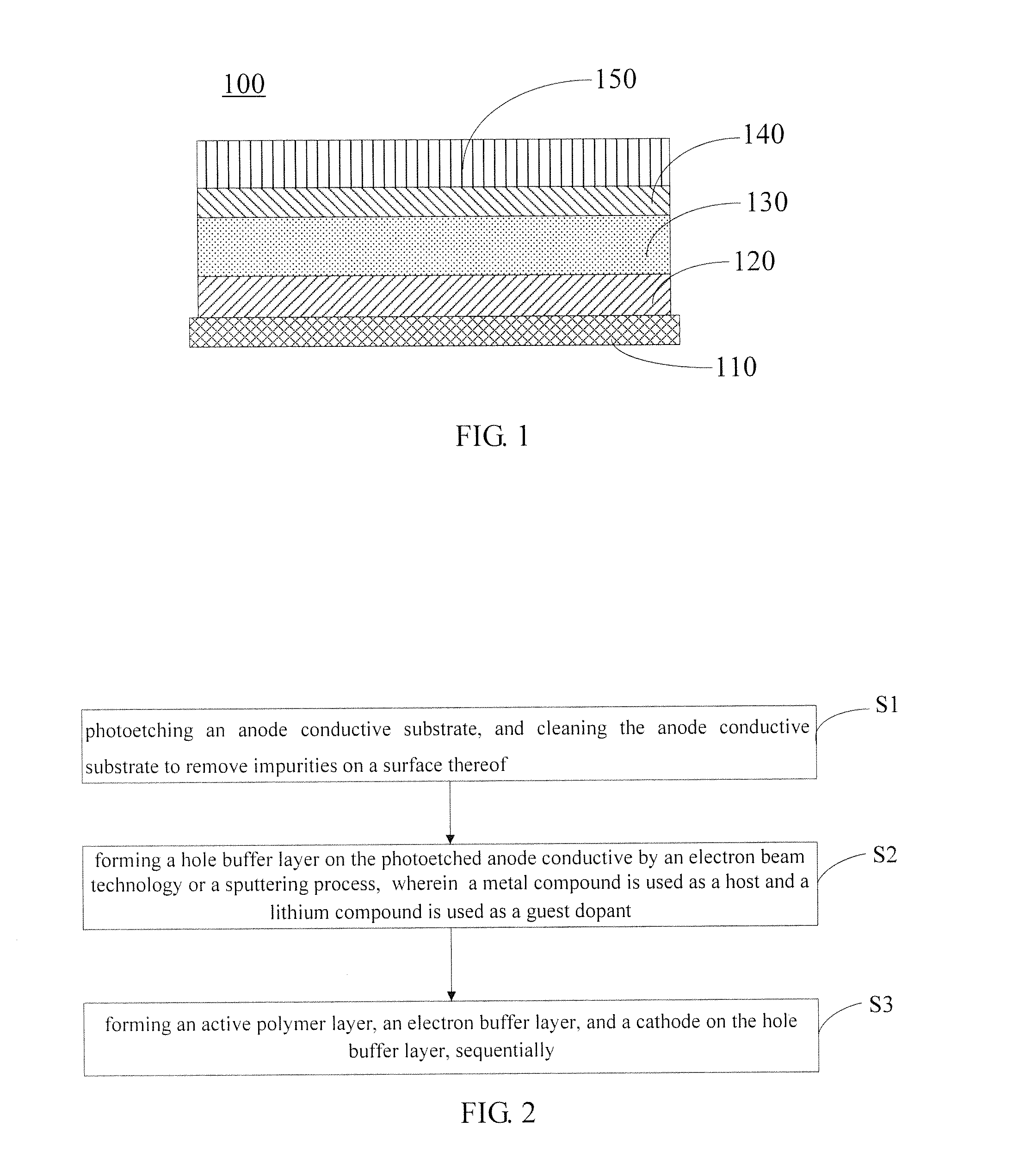
[0053]The ITO was photoetched and cut into pieces with required size, the anode conductive substrate was then treated using ultrasonic sequentially in detergent, deionized water, acetone, ethanol, and isopropyl alcohol each for 15 minutes to remove impurities on the surface of the ITO, respectively. The conductive substrate was surface-treated using oxygen plasma for 5 minutes after cleaning; the power was 10W.

[0054]The hole buffer layer with a thickness of 60 nm was formed on the surface of the ITO by electron beam technology, in which, ZnO was used as a host and Li2CO3 was used as a dopant guest, a mass ratio of Li2CO3 to ZnO was 6%.

[0055]The chlorobenzene solution of the mixture of P3HT and PCBM was then spin-coated on the hole buffer layer, and dried at a temperature of 100° C. for 30 minutes to form the active polymer layer with a thickness of 1...

example 2

[0061]The polymer solar cell has a structure of IZO / ZnS:Li2O / MEH-PPV:PCBM / CsF / Ag.

[0062]The preparation process is described as follows:

[0063]The IZO was photoetched and cut into pieces with required size, the anode conductive substrate was then treated using ultrasonic sequentially in detergent, deionized water, acetone, ethanol, and isopropyl alcohol each for 15 minutes to remove impurities on the surface of the IZO, respectively. The conductive substrate was surface-treated using oxygen plasma for 10 minutes after cleaning; the power was 50W.

[0064]The hole buffer layer with a thickness of 100 nm was formed on the surface of the IZO by magnetron sputtering process, in which, ZnS was used as a host and Li2O was used as a dopant guest, a mass ratio of Li2O to ZnS was 10%.

[0065]The xylene solution of the mixture of MEH-PPV and PCBM was then spin-coated on the hole buffer layer. and dried at a temperature of 70° C. for 100 minutes to form the active polymer layer with a thickness of 30...

example 3

[0068]The polymer solar cell has a structure of FTO / CdS:LiCl / MDMO-PPV:PCBM / LiF / Au.

[0069]The preparation process is described as follows:

[0070]The FTO was photoetched and cut into pieces with required size, and the anode conductive substrate was then treated using ultrasonic sequentially in detergent, deionized water, acetone, ethanol, and isopropyl alcohol each for 15 minutes to remove impurities on the surface of the FTO, respectively. The conductive substrate was surface-treated using oxygen plasma for 15 minutes after cleaning; the power was 30W.

[0071]The hole buffer layer with a thickness of 10 nm was formed on the surface of the FTO by electron beam technology, in which, CdS was used as a host and LiCl was used as a dopant guest, a mass ratio of LiCl to CdS was 1%.

[0072]The chlorobenzene solution of the mixture of MDMO-PPV and PCBM was spin-coated on the hole buffer layer, and dried at a temperature of 200° C. for 10 minutes to form the active polymer layer with a thickness of ...


PUM

PropertyMeasurementUnit
thicknessaaaaaaaaaa
thicknessaaaaaaaaaa
thicknessaaaaaaaaaa

Abstract

The present invention relates to a polymer solar cell and a method for preparing the same. The cell comprises a conductive anode substrate, a hole buffer layer, an active polymer layer, an electron buffer layer and a cathode laminated in succession, wherein the hole buffer layer comprises a metal compound host and a guest doped in the metal compound host, the metal compound host being one selected from ZnO, ZnS and CdS and the doped gust being one selected from Li2CO3, Li2O, LiF, LiCl and LiBr. By doping a lithium compound with few electrons as a dopant into the metal compound host, a p-type doped layer facilitating the hole transportation is formed in the polymer solar cell. The dopant and the metal compound host have stable properties and would not corrode the conductive anode substrate, facilitating industrial production in the future and effectively improving the energy conversion efficiency of the polymer solar cell.

Description

FIELD OF THE INVENTION[0001]The present disclosure relates to a field of solar cell, and more particularly relates to a polymer solar cell and a method for preparing the same.BACKGROUND OF THE INVENTION[0002]In 1982, Weinberger et al, researched the photovoltaic properties of polyacetylene and prepared the first true sense of solar cell. Subsequently, Glenis et al. prepared a variety of solar cells of polythiophene. These solar cells had problems of very low open circuit voltage and photoelectric conversion efficiency. Until 1986, C. W. Tang et al. introduced the p-type semiconductor and the n-type semiconductor into devices of bilayer structure for the first time, the level of the photocurrent had been improved greatly, and the organic polymer solar cells had flourished since this work which is regarded as a milestone.[0003]In 1992, Sariciftci et al. found that there was a phenomenon of rapid light-induced electron transfer in the composite system of 2-methoxy-5-(2-ethyl-hexyloxy)-...

Claims


Application Information

Patent Timeline
Patent Type & Authority Applications(United States)
IPC IPC(8): H01L51/44H01L51/00
CPCH01L51/4246H01L51/4253H01L51/0036H01L51/441Y02E10/549H01L51/0035H01L51/0038H10K85/114H10K85/113H10K30/211H10K30/30Y02P70/50H10K2102/00H10K30/81H10K85/111
Inventor ZHOU, MINGJIEWANG, PINGHUANG, HUIZHANG, ZHENHUA
Owner OCEANS KING LIGHTING SCI&TECH CO LTD
Why Eureka
Try Eureka