Hollow fiber cartridges and components and methods of their construction

a technology of hollow fiber cartridges and components, which is applied in the field of production and assembly of hollow fiber modules, can solve the problems of hfc without adapters for directing retentate inflow and outflow to and from the hollow fibers, complicating cleaning, sterilization and validation of a process using such a complex system, and hfm to a larger scale system containing multiple modules, so as to reduce heat-induced stresses and reduce heat-induced stresses , the effect o

Active Publication Date: 2014-10-30
REFINE TECHNOLOGY LLC
View PDF1 Cites 21 Cited by
  • Summary
  • Abstract
  • Description
  • Claims
  • Application Information

AI Technical Summary

Benefits of technology

[0050]The invention relates to hollow fiber cartridges whose structure allows the heat induced stresses that occur during the cartridges' uses to be minimized. The reduction of heat-induced stresses is achieved by the use of materials of similar identical coefficients of expansion especially with regards to the outer shell of the cartridge and the shell end caps. The cartridges are further optimized because their fibers are organiz...

Problems solved by technology

The HFC lacks the adapters for directing retentate inflow and outflow to and from the hollow fibers.
The complexity of the manifold with its interconnecting tubing, pipes, valves, and monitoring instruments, greatly complicates cleaning, sterilization, and validation of a process using such a complex system.
These are critical issues in certain industries, including the pharmaceutical, food, chemical, water, sewage treatment, etc.
Furthermore, when scaling up a process, transitioning from a smaller scale process containing a single HFM to a larger scale system containing multiple modules may complicate a critical process.
Yet, in spite of the need and benefits for large HFMs, such modules are not readily available.
Technical construction limits of such large filters may be involved.
While typical construction methods result in reliable “small to moderate” scale HFM, 2 (for a 60 cm long fiber, and 1 mm ID), they become unreliable and costly when applied to production of large filters, where large scale may be >10 m2 (for a 60 cm long fiber, and 1 mm ID).
More specifically, the complications increase for a HFM (with the same parameters) with membrane surface area >20 m2, and increase even more with even larger filters.
While it is possible to increase surface area with narrower and/or longer fibers, those options may not be desirable in many applications.
The potting material used to embed the HFs at each end of the HFC is a common source of potential problems which can become more severe as the diameter of the HFC increases.
It can cause structural failures such as cracking in the pot and/or forcing the pot to shrink inward, towards the center of a rounded potted area or along stress boundaries.
What is frequently noted is that the epoxy, with greater shrinkage than polysulfone, will pull away from the polysulfone to form a passageway between the filtrate chamber and the retentate chamber, compromising the integrity of the HFCM and rendering the HFCM useless.
Similarly, when dealing with two different materials wi...

Method used


Image

  • Hollow fiber cartridges and components and methods of their construction
  • Hollow fiber cartridges and components and methods of their construction
  • Hollow fiber cartridges and components and methods of their construction

Examples


example 1

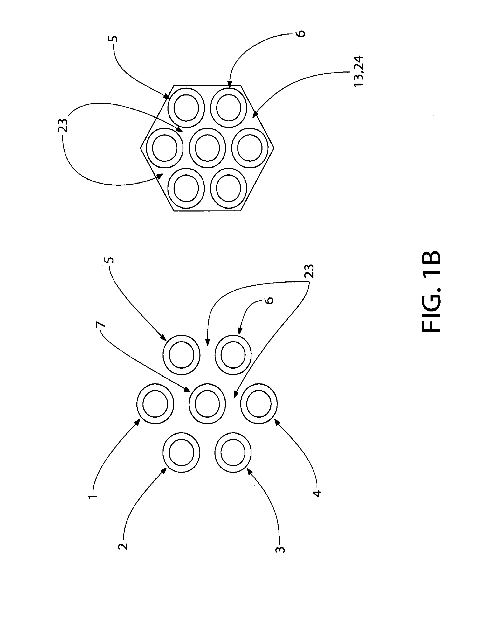
Fixing the HFs to Each Other in a Hexagonal Cluster

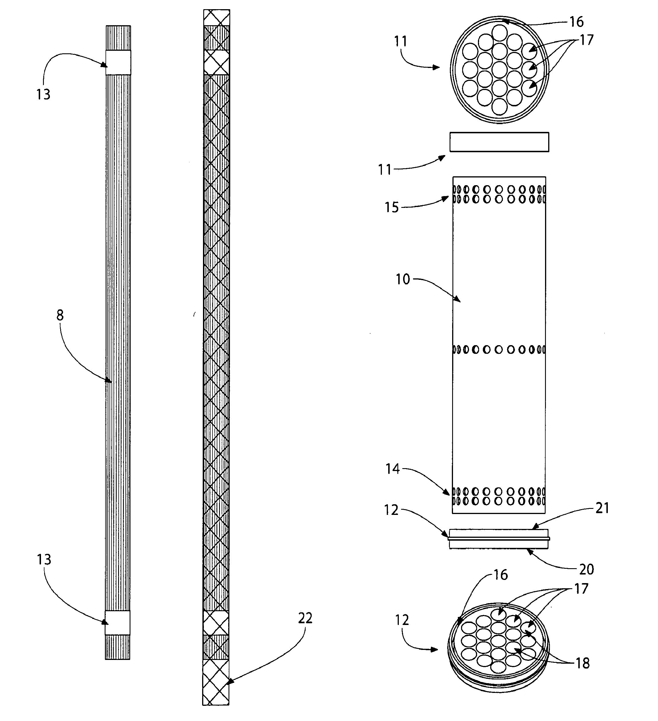
[0160]A nozzle or multiple nozzles 37, from an injector or multiple injectors may be positioned in a manner that would deliver a fixative 24 to the HF cluster in the most efficient manner. There may be various methods for delivering such fixative; in one example, a multi nozzle device 37 (FIGS. 4A, 4B: wires and tubing for fixative are shown 63) is positioned adjacent to the fibers and radially disposed about the fibers at specific intervals. The nozzles, preferably, will be mechanized such that they may move towards the cluster of HFs prior or during fixative addition and retracted after addition. During the fixative addition phase, either the HF cluster can be advanced past the nozzles to affect addition of fixative 24 over a predetermined HF segment length 13; or alternately, the HF cluster may remain stationary while the nozzle assembly 37 advances along the fibers to spread the fixative 24 over a predetermined segment length 13...

example 2

Prefabricated Cluster End Caps

[0165]To form a unit cluster (“u-cluster”), it is conceivable that the “fixing” step to form a hexagonal end cap may be accomplished without applying a liquid fixative, as previously described. The same general results may be achieved using a pre-formed cap, where such cap can be mechanically added or snapped on to the ends of the HFs. The prefabricated cap is positioned along the HF cluster so that it can be mechanically rearranged to encapsulate the fibers and at the same time, assume the desired shape, preferably the hexagonal shape. An example of such a cap is shown in FIG. 7; its two possible configurations, linear cap or segment 79 (L-cap) and folded 80 (F-cap) are shown. The two configurations are inter-convertible as will be shown. The L-cap 79 contains six sub segments, numbered sequentially 81 to 86.

[0166]Adjacent segments 81 to 86 (FIG. 7) form “U” shaped grooves, channels or wells 87. The channels are designed to be positioned parallel to th...


PUM

PropertyMeasurementUnit
Pressureaaaaaaaaaa
Pressureaaaaaaaaaa
Angleaaaaaaaaaa

Abstract

Hollow fiber cartridges and components and methods of their construction.

Description

CROSS REFERENCE TO RELATED APPLICATIONS[0001]This application claims the benefit of U.S. provisional application No. 61 / 579,623 filed Dec. 22, 2011, which application is incorporated by reference in its entirety herein.FIELD OF THE INVENTION[0002]The present invention relates to method of production and assembly of hollow fiber modules.BACKGROUND OF THE INVENTION[0003]Hollow fiber filters whose walls may be porous and semipermeable possess excellent filtration performance and properties that are applicable in many fields and applications. Hollow fibers (HFs) are used extensively in water purification, separation of constituents from biological fluids, dialysis, reverse osmosis, gas separation, cell culture devices, as well as many others. In spite the variety of uses, hollow fiber based filtration devices have a common structure and mode of operation. The filtration unit is the hollow fiber module (HFM), and while the HFM structure may vary somewhat from one application to another, ...

Claims


Application Information

Patent Timeline
IPC IPC(8): B01D63/02B01D63/04
CPCB01D63/021B01D2313/21B01D63/043B01D63/024B01D65/104B01D2313/20B01D2313/23B01D2313/54B01D2317/022B01D2313/02B01D2319/04B01D63/02B01D63/04
Inventor SHEVITZ, JERRY
Owner REFINE TECHNOLOGY LLC
Why Eureka
Try Eureka