Method of cladding and fusion welding of superalloys
a superalloy and fusion welding technology, applied in the direction of electron beam welding apparatus, machine/engine, climate sustainability, etc., can solve the problems of low ductility of turbine blades manufactured of nickel and cobalt based precipitation hardening and directionally solidified superalloys, poor mechanical properties of brazed joints that do not allow extensive dimensional restoration of turbine blades and other engine components, and the need for costly rework. , to achieve the effect of eliminating th
- Summary
- Abstract
- Description
- Claims
- Application Information
AI Technical Summary
Benefits of technology
Problems solved by technology
Method used
Image


Examples
example 1
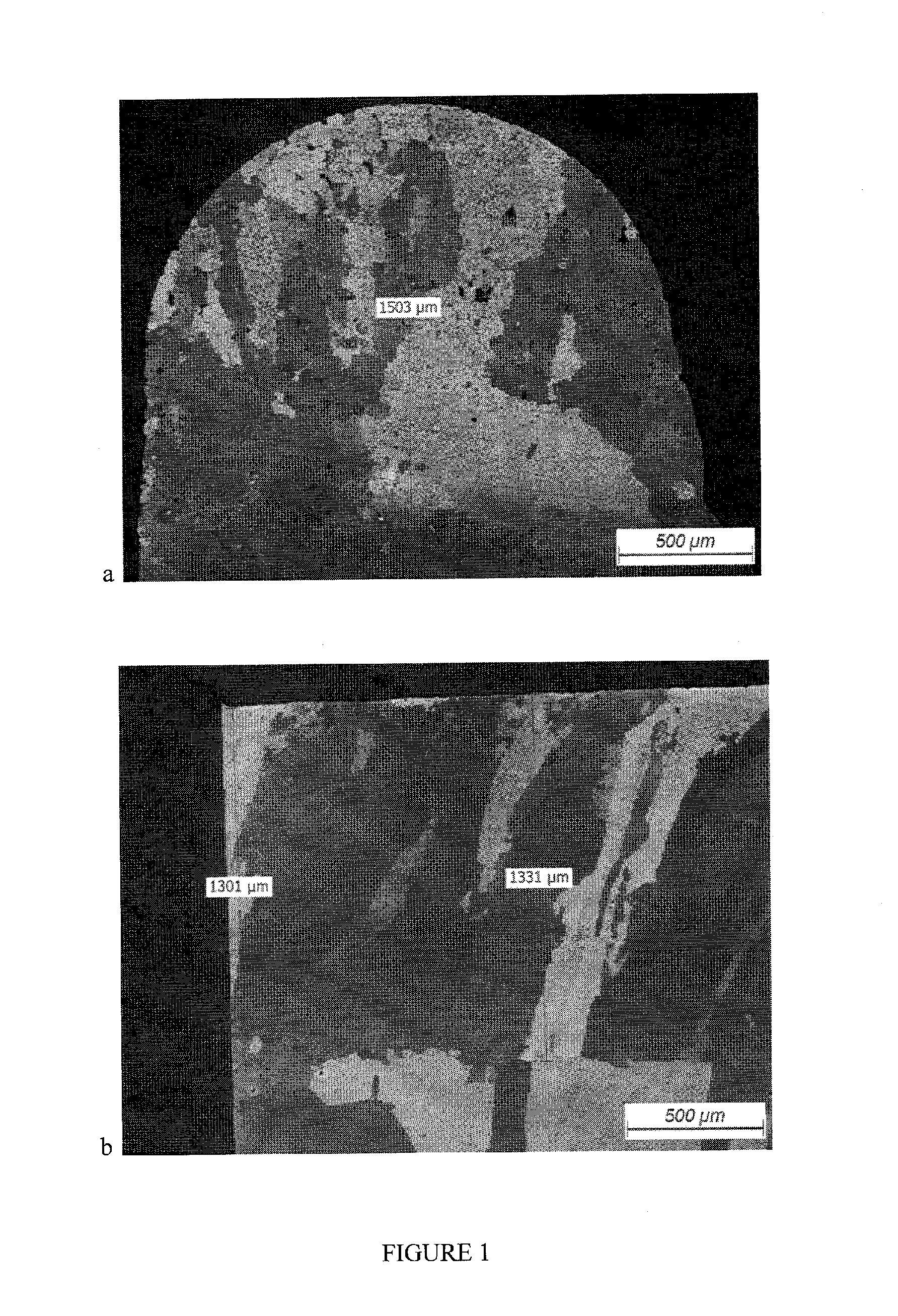
[0156]Three (3) passes automatic microplasma pulsed cladding was made at an ambient temperature using filler material comprised of 70% Mar M247 high temperature filler and 30% AWS BNi-9 brazing powders on the Inconel 738 substrate of 0.060-0.070 inch in width.
[0157]Following below parameters were used:
[0158]Traveling (welding) speed—2 ipm (inch per minute)
[0159]Powder feed rate—3 g / min
[0160]Max Weld Current—21.8 A
[0161]Min Weld Current—15.6 A
[0162]Duty Cycle—60%
[0163]Frequency—3 Hz
[0164]Shielding Gas—argon
[0166]Welded samples were subjected to a post weld heat treatment in vacuum with a pressure below of 10−4 torr at a temperature of 1120°±10° C. for two (2) hours. At this temperature the material of the clad welds was in a solid-liquid condition that allowed self healing of micro cracks in clad welds and the formation of eutectic alloy along the fusion line resulting in a healing of micro cracks.
[0167]No cracks were observed in clad welds and HAZ. Typical m...
example 2
[0168]Three (3) passes laser cladding was made at an ambient temperature using filler material comprised of 75% Inconel 738 high temperature filler and 25% AWS BNi-9 brazing powders on the Inconel 738 substrate of 0.080-0.090 inch in width at an ambient temperature.
[0169]To produce clad welds of 0.090-0.100 inch in width the laser welding head was oscillated perpendicular to the welding direction.
[0170]To minimize overheating of the substrate during the first pass and ensure good fusion between passes the laser beam power was incrementally increased from the first pass to the top (last) one.
[0171]Following below welding parameters were used:
[0172]Welding speed—3.8 ipm
[0173]Powder feed rate—6 g / min
[0174]Oscillation speed (across weld samples)—45 ipm
[0175]Oscillation distance—0.033 inch either side of the center line of the sample
[0176]Beam power: 325 W (first pass), 350 W (second pass), 400 W (third pass)
[0177]Carrier gas—argon
[0178]Shielding gas—argon
[0179]After welding samples were...
example 3
[0183]Three (3) passes laser cladding was made at an ambient temperature using filler powder comprised of 73% Inconel 738 high temperature filler and 27% AWS BNi-9 brazing powders on the Mar 002 substrate of 0.080-0.090 inch in width.
[0184]To produce clad welds of 0.090-0.100 inch in width the laser head was oscillated perpendicular to the welding direction.
[0185]Following below welding parameters were used:
[0186]Welding speed—3.8 ipm
[0187]Powder feed rate—8 g / min
[0188]Oscillation speed (across weld samples)—45 ipm
[0189]Oscillation distance—0.033 inch either side of the center line of the sample
[0190]Beam power: 475 W for all three passes
[0191]Carrier gas—argon
[0192]Shielding gas—argon
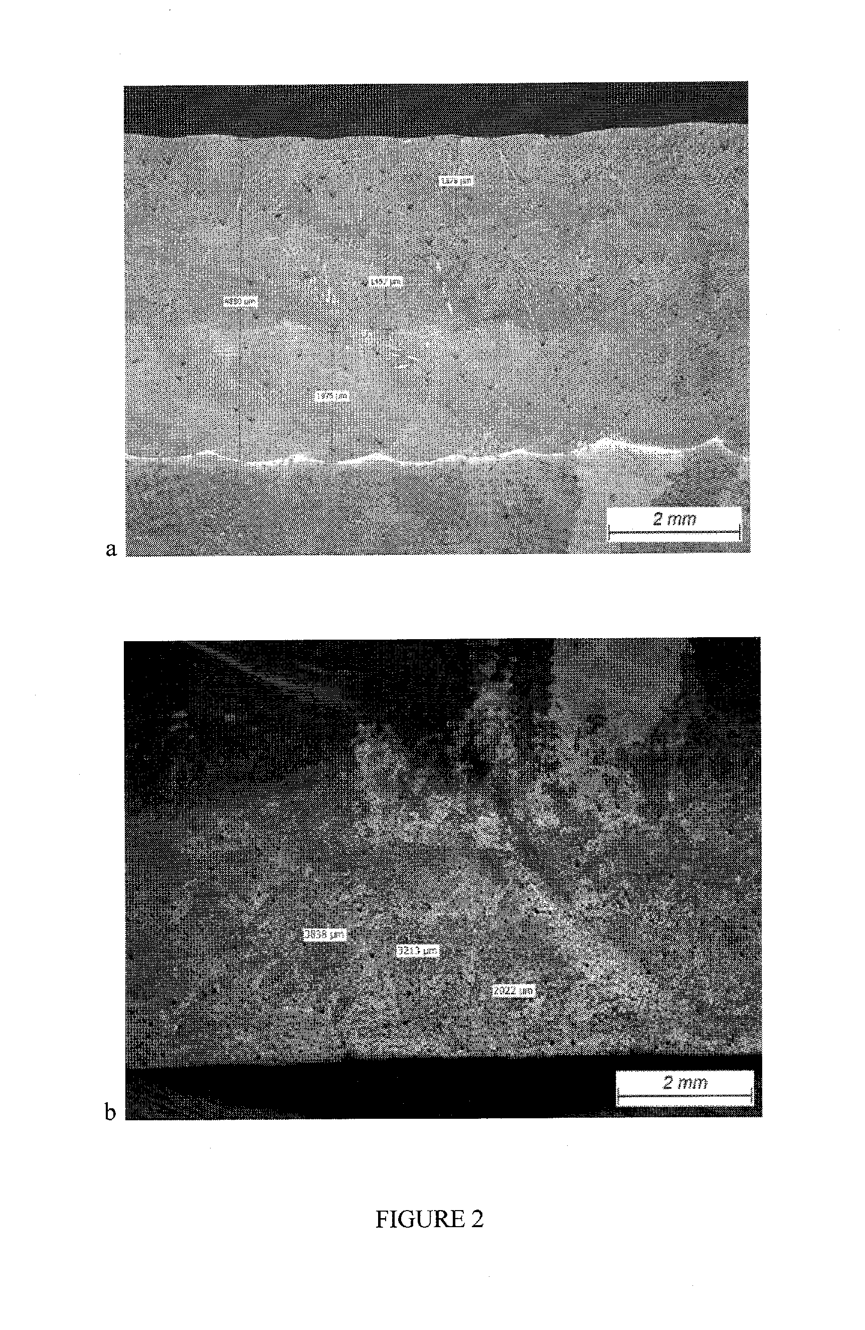
[0193]Welded samples were subjected to a post weld heat treatment in vacuum with a pressure below of 10−4 torr at a temperature of 1200°±10° C. for two (2) hours. At this temperature the material of the clad welds was in a solid-liquid condition that allowed self healing of micro cracks in the welds. W...
PUM
| Property | Measurement | Unit |
|---|---|---|
| Temperature | aaaaa | aaaaa |
| Fraction | aaaaa | aaaaa |
| Fraction | aaaaa | aaaaa |
Abstract
Description
Claims
Application Information
 - R&D
- Intellectual Property
- Life Sciences
- Materials
- Tech Scout
- Unparalleled Data Quality
- Higher Quality Content
- 60% Fewer Hallucinations
Browse by: Latest US Patents, China's latest patents, Technical Efficacy Thesaurus, Application Domain, Technology Topic, Popular Technical Reports.
© 2025 PatSnap. All rights reserved.Legal|Privacy policy|Modern Slavery Act Transparency Statement|Sitemap|About US| Contact US: help@patsnap.com