
LPG Fuel System

Inactive Publication Date: 2015-05-28
GREENKRAFT INC
View PDF5 Cites 5 Cited by
  • Summary
  • Abstract
  • Description
  • Claims
  • Application Information

AI Technical Summary

Benefits of technology

The patent text describes a fuel system for reducing exhaust emissions and increasing combustion efficiency in LPG-fuelled engines. The system includes a pressure sensor to monitor vapor pressure in the tank and a pump to circulate liquid propane through a heat exchanger to keep the tank pressure within a certain range. The technology allows for complete combustion of the air / fuel mixture with reduced exhaust emissions and improved fuel economy. Overall, the invention aims to improve the performance and reduce emissions of LPG-fuelled vehicles.

Problems solved by technology

Although capable of resulting in a combustible mixture of air and LPG, known LPG fueling systems have not been entirely satisfactory for use in automobiles.
One reason for the unsatisfactory aspects of known systems is that the systems mix vaporized air and LPG vapor at different kinetic energies, so that mixing is not thorough and the mixture or portions of the mixture are outside of the preferable flammability limits.
Even when an LPG-air mixture is within the flammability limits, other problems can arise based on the mixture's ratio of LPG to air.
When there is too little LPG in the LPG-air mixture, the mixture burns poorly and the combustion exhaust will have high mono-nitrogen oxide (NOx) levels.
A situation of too much or either too little LPG is undesirable because: (1) unburned air-fuel mixtures result in low fuel economy or efficiency and unclean (spark knock) burning that causes reduced engine power, and (2) increased levels of NOX, CO, and HC in the exhaust that result in higher carbon dioxide (CO2) emissions after catalytic conversion.
Ordinary automotive engines and fuel delivery systems are also very inefficient for mixing vaporized LPG with air.
One cause of the inefficiency pressure differential between the atmosphere and the intake manifold.
This variation can result in inconsistent LPG-air mixture burn.
But, throttled air is problematic because such air can require additional energy for vaporization of the LPG and mixing of the LPG and air.
Another problem with current LPG systems is that once the LPG is injected into the cylinder head's intake port, mixture velocity of the air and LPG is often so high that some of the fuel droplets are centrifuged out of the air stream as the air stream enters the combustion chamber.
Each portion of the mixture has an unfavorable fuel to air ratio despite the overall air / fuel ratio of the whole being correct when it entered the combustion chamber.
While the portions may combust, one section has too much LPG and another section has too little.
The mixture portion with too much LPG will result in carbon residues accumulating in the combustion chambers and on the piston tops.
Portions of the mixture with too little LPG will burn poorly and increase NOX levels.
Too little LPG can also result in high localized temperatures that can cause auto-ignition or detonation of the end gases, which can be destructive.
Known LPG fuel systems are also problematic for internal combustion engines.
Then, when the spark plug tries to ignite these portions of the mixture, a flame front is created and the fuel does not combust correctly.
Later, during the power stroke of the engine, pressure in the cylinder and the boiling point of the mixture decreases and the unburned fuel evaporates and burns.
This is problematic because if the fuel burns too late, it can interfere with an optimal crankshaft angle for producing power and produces high exhaust gas temperatures that require larger cooling systems and wasted energy.
Catalytic converters solve some of the problems of inefficiency and pollution associated with current LPG systems, but not all of them.
Furthermore, currently produced catalytic converters are only effective when the engine is at operating temperature, so they have no effect on cold start emission levels.

Method used


Image

  • LPG Fuel System
  • LPG Fuel System
  • LPG Fuel System

Examples


Embodiment Construction

[0031]Generally disclosed is a LPG fuel system. In operation, the invention is accomplished by mixing vaporized LPG with air when the vapor and the air have either balanced heat loads or substantially equalized random kinetic energies. In one embodiment, the balanced heat loads or equalized random kinetic energies between the air and vaporized LPG can be produced by (1) pumping LPG fuel from a fuel tank through a heat exchanger, wherein heat from engine coolant is used to vaporize the LPG fuel; (2) returning the vaporized LPG to the fuel tank so that LPG fuel and vaporized LPG fuel occupy the fuel tank; and (3) mixing vaporized LPG fuel with air from the atmosphere.

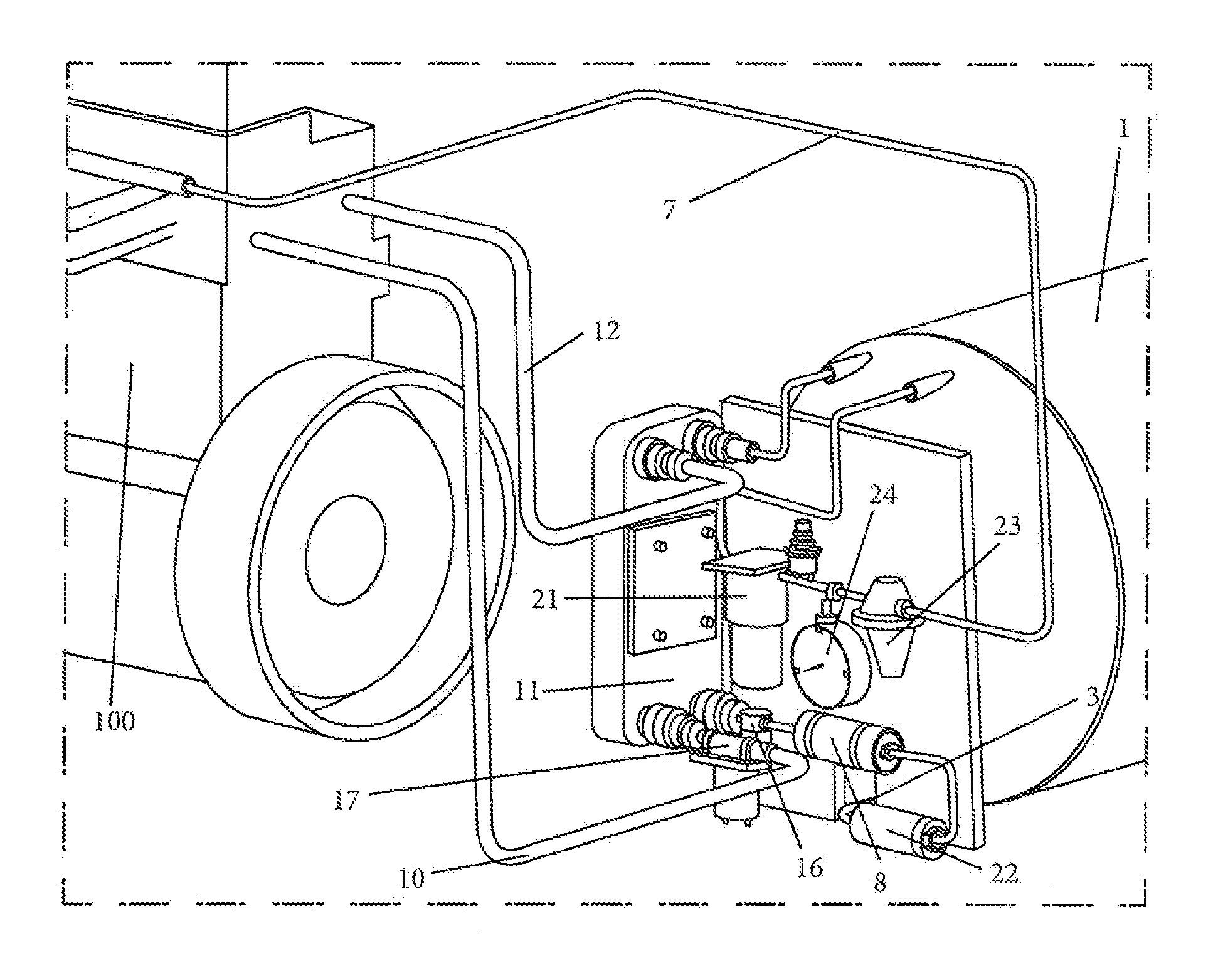
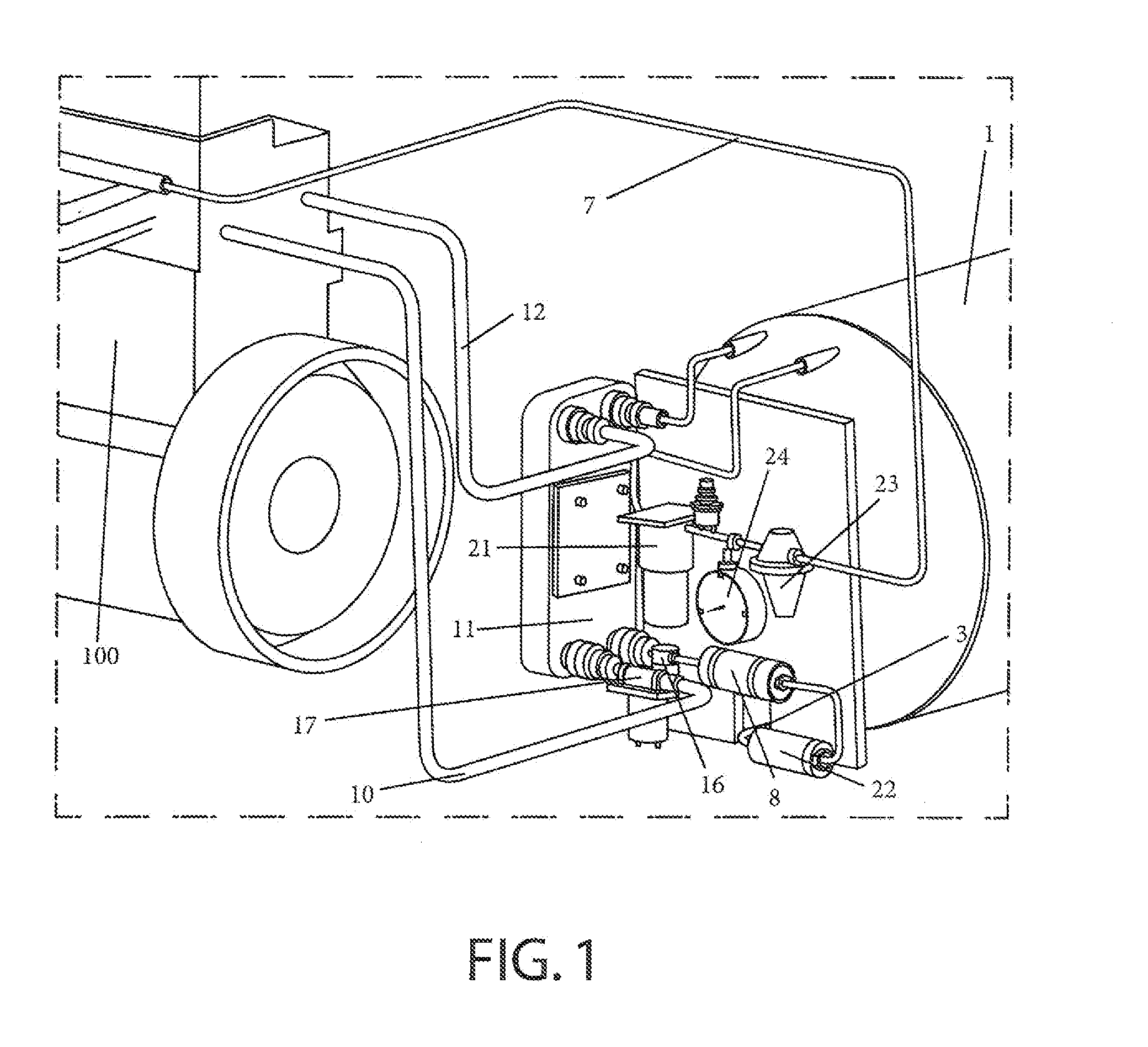
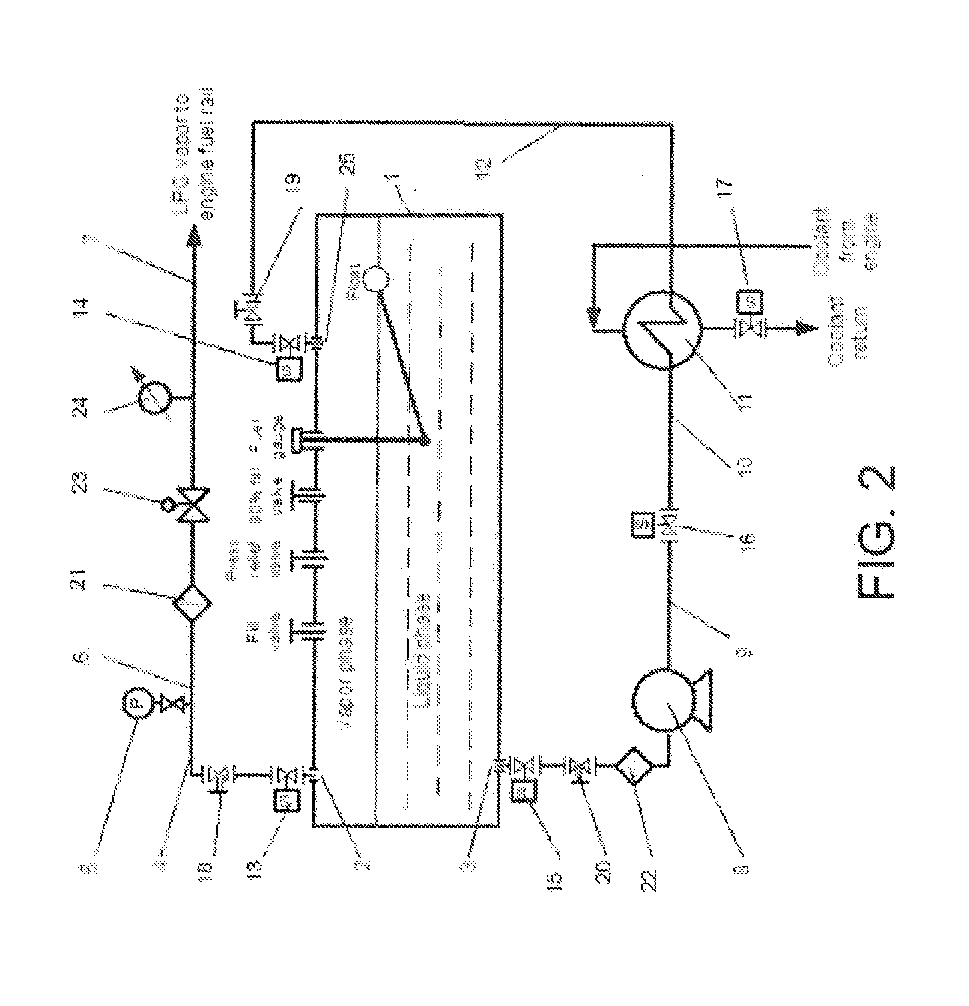
[0032]FIG. 1 is an environmental view of one embodiment of the LPG fuel system for internal combustion engines. In use, LPG fuel may be drawn from the fuel tank 1 through a pipe 3 and a first filter 22 via an electric fuel pump 8. The fuel passes through a fuel solenoid valve 16 into a heat exchanger 11 and then is return...


PUM


Abstract

Disclosed is a liquefied petroleum fuel system for internal combustion engines that improves fuel economy by mixing vaporized liquid petroleum gas (LPG) and ambient air at substantially equal random kinetic energies. The system maintains a certain vapor pressure in the LPG tank and delivers the LPG in a gaseous phase to an LPG burning device at a set pressure and temperature. The cycle repeats as necessary to maintain the desired pressure in the tank.

Description

CROSS-REFERENCE TO RELATED APPLICATIONS[0001]This application claims the priority benefit of U.S. Prov. Pat. App. Ser. No. 61 / 908,022 (filed Nov. 22, 2013) and entitled LPG Fuel System which provisional patent application is hereby incorporated by reference in its entirety.STATEMENT REGARDING FEDERALLY SPONSORED RESEARCH OR DEVELOPMENT[0002]Not Applicable.BACKGROUND OF INVENTION[0003]1. Field of the Invention[0004]The subject matter of this disclosure is in the field of systems for Liquefied Petroleum Gas (LPG) fuel systems for internal combustion engines and related methods. More specifically, the subject matter of this disclosure is related to LPG fuel systems for internal combustion engines of road vehicles, stationary machines, marine vehicles, and gas turbines.[0005]2. Background of the Invention[0006]LPG is a fossil fuel that is prepared by refining petroleum or natural gas. The refined gas results in several types of liquid fuel, including: propane, butane, or isobutane. In o...

Claims


Application Information

Patent Timeline
IPC IPC(8): F02M21/06F02M21/04
CPCF02M21/04F02M21/06F02M21/0212F02M21/0221F02M21/023F02M21/0287Y02T10/30F02D19/0647
Inventor HARNESS, HENRY
Owner GREENKRAFT INC
Learn More