Solid electrolyte
- Summary
- Abstract
- Description
- Claims
- Application Information
AI Technical Summary
Benefits of technology
Problems solved by technology
Method used
Image

Examples
production example 1
Production of Lithium Sulfide (Li2S)
[0237]Lithium sulfide was produced and purified in accordance with the method described in the Examples of WO2005 / 040039A1. Specifically, it was produced and purified as follows.
(1) Production of Lithium Sulfide
[0238]In a 10 liter-autoclave provided with a stirring blade, 3326.4 g (33.6 mol) of N-methyl-2-pyrrolidone (NMP) and 287.4 g (12 mol) of lithium hydroxide were charged, stirred at a speed of 300 rpm and heated to 130° C. After the heating, hydrogen sulfide was blown to the liquid at a supply speed of 3 liter / min for 2 hours.
[0239]Subsequently, the reaction liquid was heated in a nitrogen stream (200 cc / min), and part of the reacted hydrogen sulfide was dehydrosulfurized. As the temperature was elevated, water produced as a by-product by the reaction of hydrogen sulfide and lithium hydroxide starts to evaporate. This water was condensed by means of a condenser and withdrawn outside the system. With distillation off of the water outside the ...
example 1
Raw Material Ratio:Li2S / P2S5 / LiBr=75 / 25 / 16.8):MM Method
[0242](1) Synthesis of solid electrolyte glass
[0243]0.337 g (0.00717 mol) of lithium sulfide produced in Production Example 1, 0.532 g (0.00239 mol) of phosphorus pentasulfide (manufactured by Sigma-Aldrich Co.) and 0.140 g (0.00161 mol) of lithium bromide (manufactured by Sigma-Aldrich Co.) were mixed sufficiently in a glove box in an argon atmosphere. Then, the mixed power and 10 zirconia balls (each having a diameter of 10 mm) were put in an alumina pot of a planetary ball mill (P-7; manufactured by Fritsch) and completely sealed. The inside of the pot was argon atmosphere.
[0244]For initial several minutes, the planetary ball mill was rotated at a low speed (100 rpm) to mix lithium sulfide and phosphorus pentasulfide sufficiently. Thereafter, the rotation speed of the planetary ball mill was raised gradually to 370 rpm. With the rotation speed of the planetary ball mill being 370 rpm, mechanical milling was conducted for 20 h...
example 2
Raw Material Ratio:Li2S / P2S5 / LiBr=77 / 23 / 17.3):MM Method
[0262]A solid electrolyte glass and a solid electrolyte glass ceramic were produced and evaluated in the same manner as in Example 1, except that the raw materials were changed to 0.349 g (0.0076 mol) of lithium sulfide, 0.503 g (0.00227 mol) of phosphorus pentasulfide (manufactured by Sigma-Aldrich Co.), and 0.148 g (0.00171 mol) of lithium bromide (manufactured by Sigma-Aldrich Co.) and the heat treatment temperature for allowing the glass to be glass ceramic was changed to 220° C. The results are shown in Table 1.
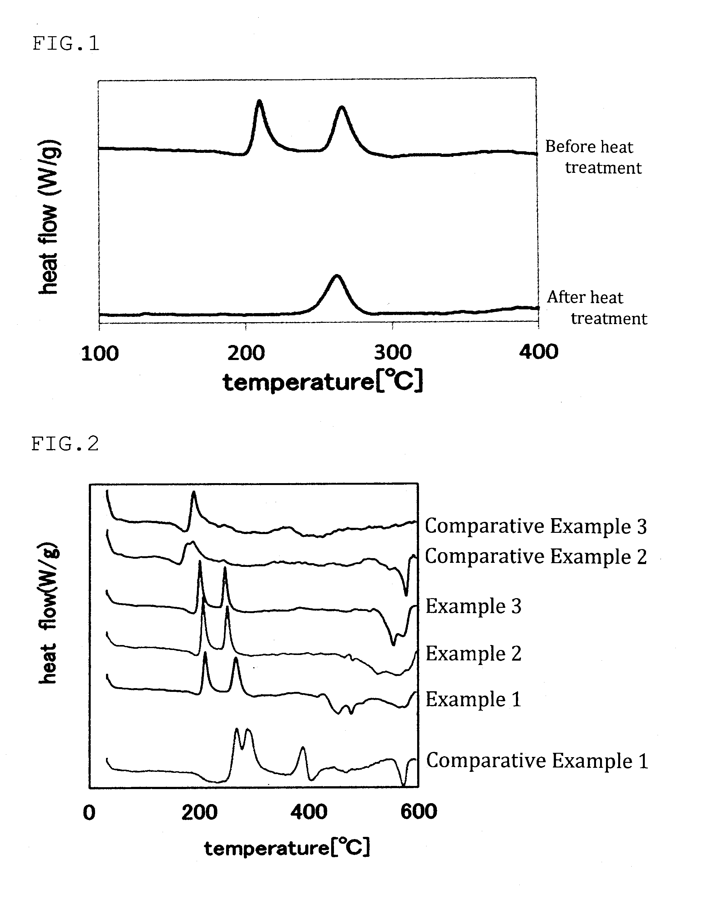
[0263]The results of the differential thermal analysis of the solid electrolyte glass are shown in FIG. 2.
PUM
| Property | Measurement | Unit |
|---|---|---|
| Temperature | aaaaa | aaaaa |
| Temperature | aaaaa | aaaaa |
| Temperature | aaaaa | aaaaa |
Abstract
Description
Claims
Application Information
 - Generate Ideas
- Intellectual Property
- Life Sciences
- Materials
- Tech Scout
- Unparalleled Data Quality
- Higher Quality Content
- 60% Fewer Hallucinations
Browse by: Latest US Patents, China's latest patents, Technical Efficacy Thesaurus, Application Domain, Technology Topic, Popular Technical Reports.
© 2025 PatSnap. All rights reserved.Legal|Privacy policy|Modern Slavery Act Transparency Statement|Sitemap|About US| Contact US: help@patsnap.com