
Battery

a battery and battery technology, applied in the field of batteries, can solve the problems of high manufacturing threshold, high cost, safety risk, and low reliability of conventional lithium-ion batteries, and achieve the effect of reducing the risk of safety hazards, and reducing the cost of lithium-ion batteries

Active Publication Date: 2015-10-29
POSITEC POWER TOOLS (SUZHOU) CO LTD +1
View PDF2 Cites 14 Cited by
  • Summary
  • Abstract
  • Description
  • Claims
  • Application Information

AI Technical Summary

Benefits of technology

The present invention is a low-cost, safe, reliable and excellent performance battery that can be used as an energy storage system in the field of large-scale energy storage. It has a long life cycle, stable operation modes and can be used as a substitute for lead-acid battery. The battery has a porous layer or graphene layer on the anode that provides a large specific surface area for the deposition of active ions and restrains the dendrite of anode, ensuring the battery of excellent performance and life. The concentration of active ion and intercalation-deintercalation ion is proper in electrolyte within the pH range 3-7, ensuring the capacity of battery. Additionally, a method of passivating current collector is also provided.

Problems solved by technology

However, no kind of batteries are able to satisfy cost, reliable, safe and long life requirements simultaneously.
Conventional lithium-ion batteries are expensive and of safety risk; sodium-sulfur battery is expensive and of high manufacturing threshold; several technology bottlenecks of vanadium redox flow battery are currently unable to solve.
In 1994, Jeff Dahn et al. presented an aqueous battery with LiMn2O4 as the cathode material, vanadium oxide such as LiV3O8 as the anode material, and a water solution of lithium salts as the electrolyte, but the toxicity of vanadium and poor stability of anode in water limit the development of this kind of battery.

Method used


Image

  • Battery
  • Battery
  • Battery

Examples


embodiment 1

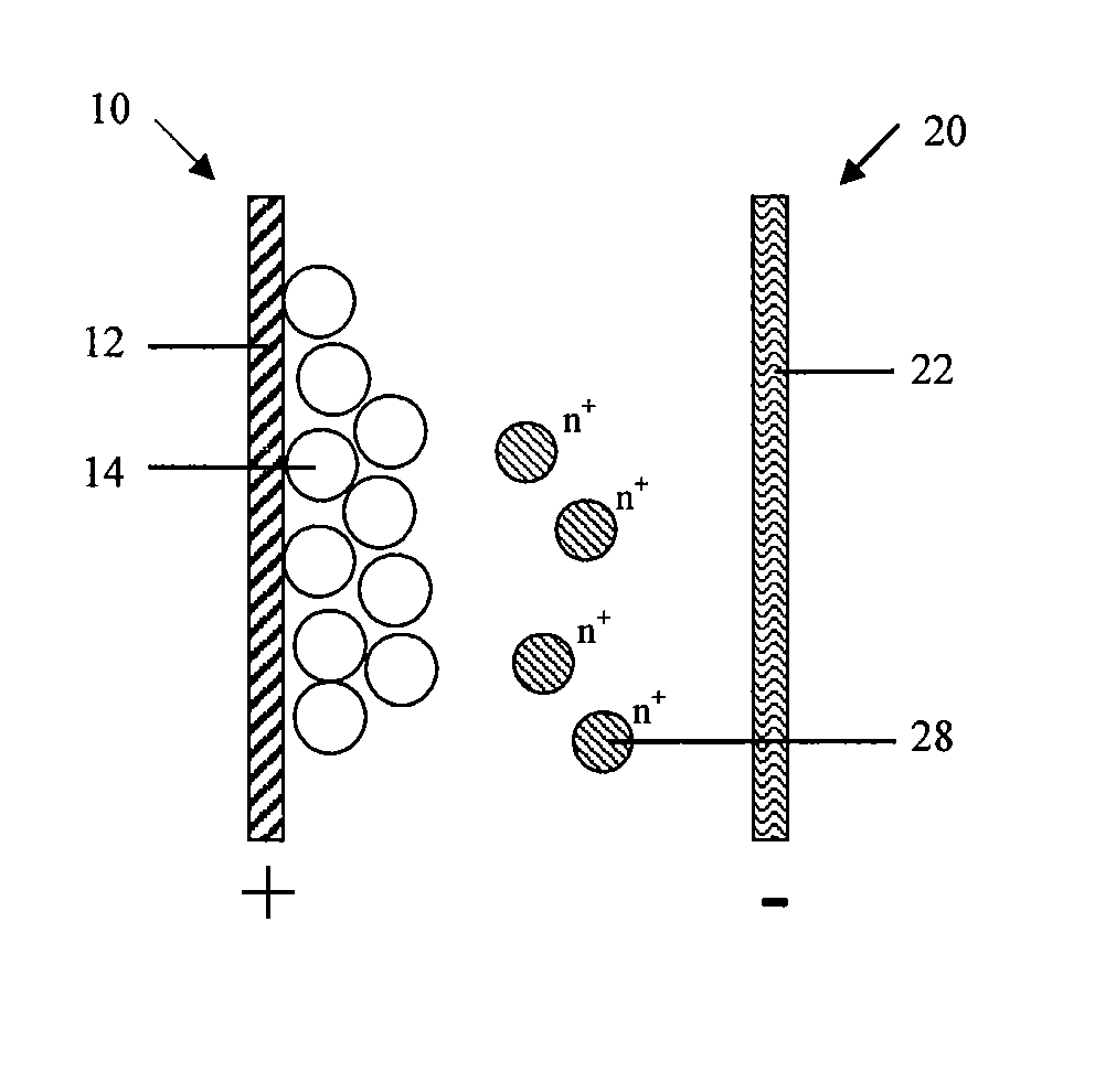
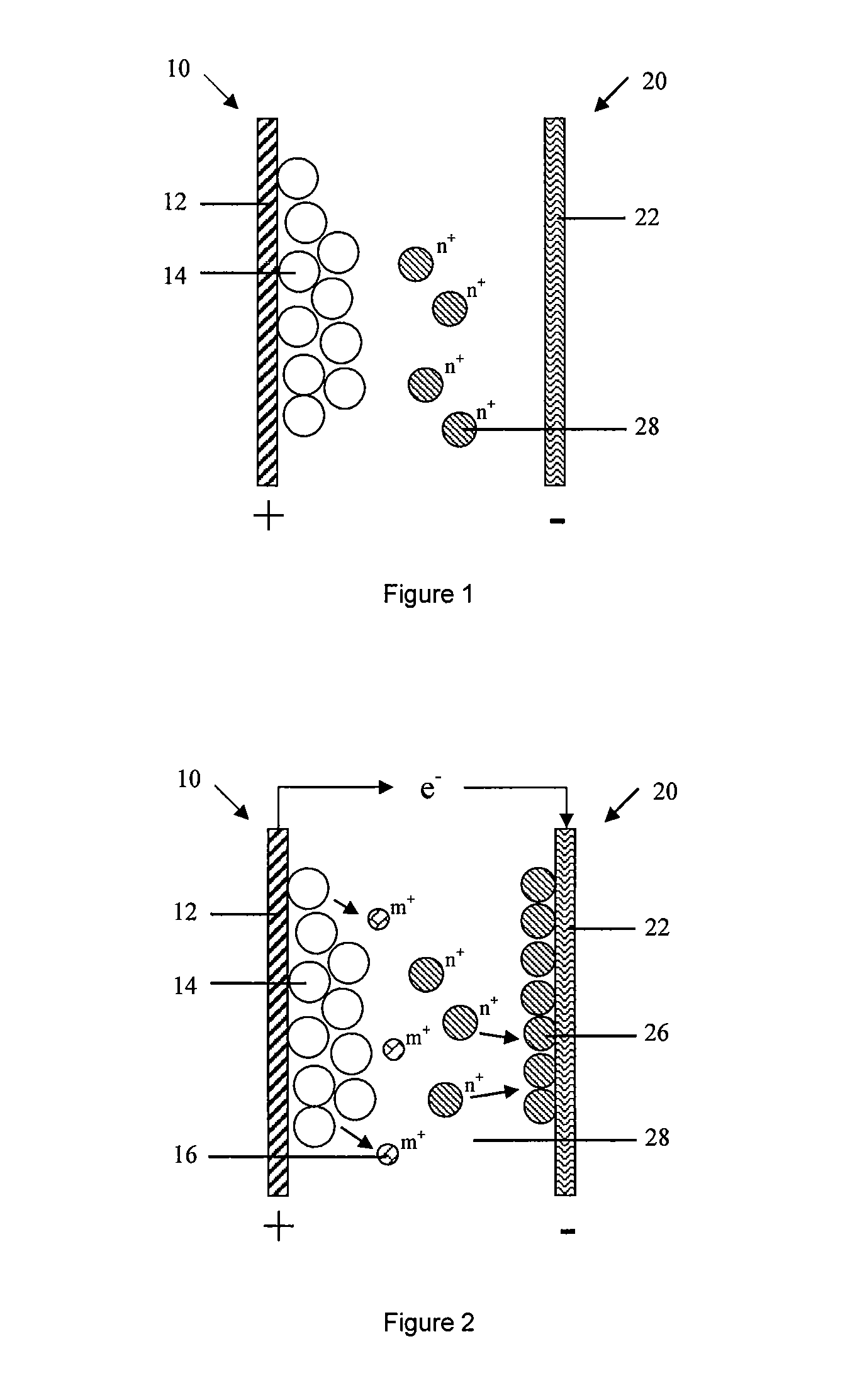
[0123]The battery comprises a cathode 10, an anode 20 and an electrolyte (not shown in Figures). The cathode 10 comprises a cathode current collector 12 and a cathode active material 14 which participates in the electrochemical reaction; the anode 20 at least comprises an anode current collector 22; the electrolyte comprises at least one solvent capable of dissolving solute, solute being ionized to at least an active ions 28 that can be reduced to a metallic state during the charge cycle and oxidized from the metallic state to the dissolved ion state during the discharge cycle.

[0124]As shown in FIG. 1, FIG. 1 schematically shows the battery structure in the first embodiment in which anode 20 only comprises an anode current collector 22.

[0125]The cathode active material 14 participates in the cathode reaction which is capable of reversibly intercalating-deintercalating ions or functional group. Specifically, the cathode active material 14 is capable of reversibly intercalating-deinte...

embodiment 2

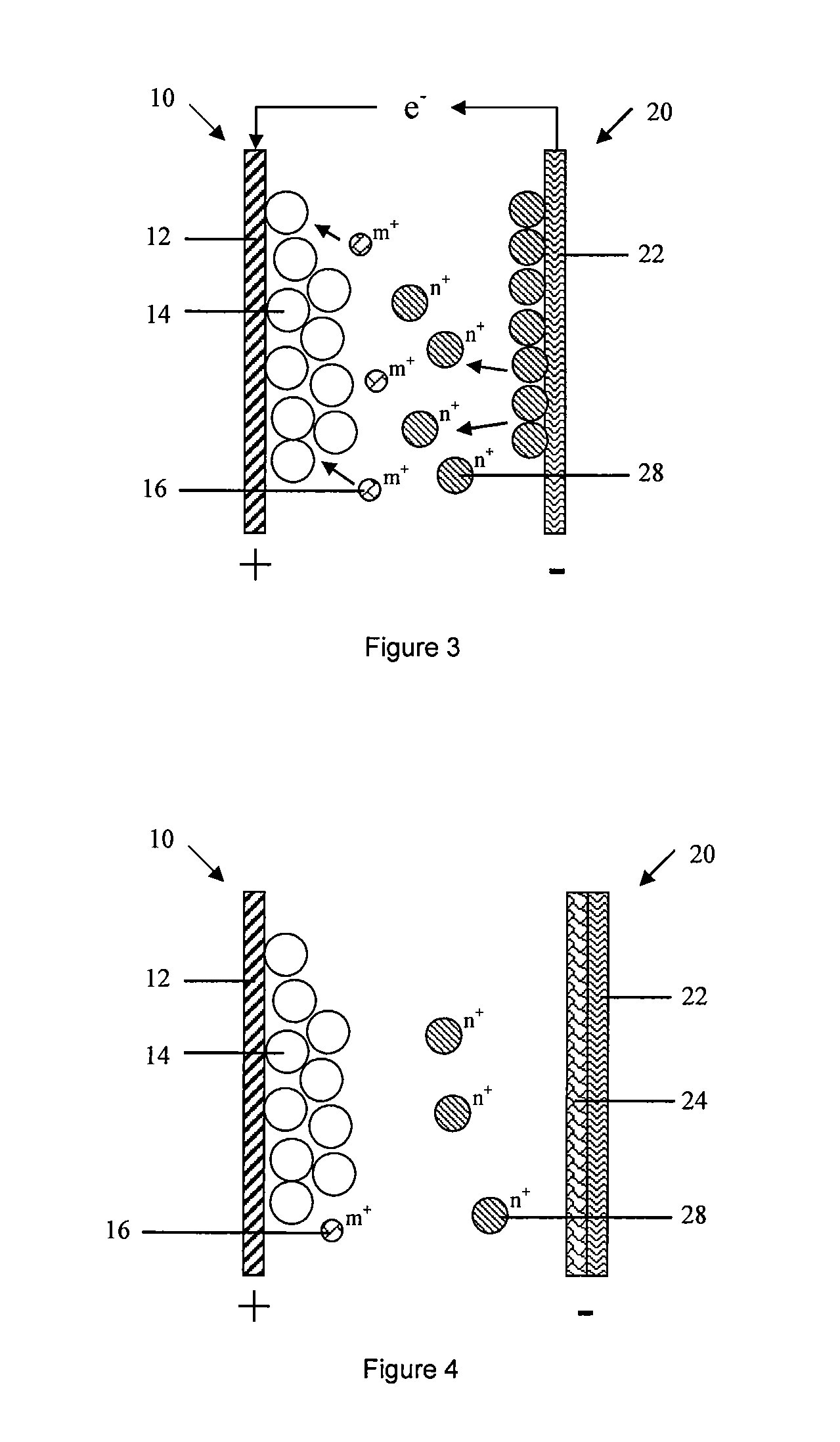
[0170]As shown in FIG. 4, The second embodiment of the present invention provides a battery, the typical difference of battery in embodiment 1 and 2 is: anode 20 in the second embodiment further comprises an anode active material formed on the anode current collector 22, which can be oxidized and dissolved to the active ion state during the discharging process.

[0171]The anode current collector 22 served as a carrier of electronic conduction and collection does not participate in the electrochemical reaction. Anode active material 24 is formed on the anode current collector 22 by the means of coating, electroplating or sputtering. The method of sputtering includes but not limited to magnetron sputtering, in specific, anode current collector 22 is Cu foil, anode active material 24 is Zn, Zn is formed on the surface of Cu foil by electroplating.

[0172]Preferably, the anode active material 24 is formed on the surface of anode current collector 24 being suffered a surface pre-treatment; t...

embodiment 3

[0200]The third embodiment of the present invention provides a battery, the typical difference of battery in embodiment 3 and 2 is: anode 20 in the embodiment 3 only comprises an anode current collector 22, which is not served as a carrier for electron conduction and collection, but also participating in anode reaction as anode active material. Anode current collector can be oxidized and dissolved to active ion state during the discharge cycle, such as active ion 28 is Zn2+, anode current collector is Zn correspondingly.

[0201]In embodiment 3, anode 20 comprises an anode current collector that participates in electrochemical reaction, a porous layer or graphene layer is formed on the surface of anode current collector. More specifically, cathode active material is LiMn2O4, cathode current collector 12 is stainless steel net, anode current collector 22 is Zn, and electrolyte comprises water solution with Zn salt. Preferably, electrolyte comprises Zn salt and Li salt. Metal Zn can part...


PUM

PropertyMeasurementUnit
thicknessaaaaaaaaaa
cut-off aaaaaaaaaa
cut-off aaaaaaaaaa

Abstract

A battery, including a cathode, an anode, an electrolyte; the cathode including a cathode active material capable of reversibly intercalating-deintercalating ions; the anode including an anode current collector that does not participate in the electrochemical reaction; the electrolyte including a solvent capable of dissolving solute, the solute being ionized to at least an active ions that can be reduced to a metallic state during a charge cycle and be oxidized from the metallic state to the dissolved ion state during a discharge cycle and / or an intercalation-deintercalation ions that can deintercalate from the cathode active material during the charge cycle and intercalate into the cathode active material during the discharge cycle; the anode further comprising an anode active material formed on the anode current collector capable of being oxidized and dissolved to active ion state during the discharge cycle.

Description

CROSS-REFERENCES TO RELATED APPLICATIONS[0001]This application claims priority from PCT Application No. PCT / CN2012 / 076413, filed Jun. 3, 2012 incorporated by reference in its entirety.FIELD OF THE INVENTION[0002]The present invention relates to an electrochemical energy storage technology. In particular, the invention relates to a battery.BACKGROUND[0003]The wide use of new energy leads to a rapid expansion of secondary battery market. The demand of secondary battery is sharply increased. A cheap, reliable, safe and long-life secondary battery is in urgent requirement no matter in electric vehicles, wind power, solar energy grid or regulation peak load. The current development of secondary battery mainly focuses on lithium-ion batteries, high temperature sodium-sulfur batteries, sodium nickel batteries and vanadium redox flow battery. These batteries have their advantages, such as lithium-ion batteries and sodium-sulfur battery with long life and high energy density, vanadium redox ...

Claims


Application Information

Patent Timeline
Patent Type & Authority Applications(United States)
IPC IPC(8): H01M4/38H01M4/62H01M4/66H01M4/64H01M4/04
CPCH01M4/38H01M4/64H01M4/0404H01M2220/20H01M4/661H01M4/625H01M4/0426H01M4/045H01M4/134H01M4/1395H01M4/485H01M4/505H01M4/525H01M4/587H01M4/622H01M4/662H01M4/663H01M4/666H01M4/667H01M4/669H01M4/80H01M10/0525H01M10/36H01M2220/30H01M2300/0002H01M2300/0005Y02E60/10Y02P70/50H01M4/0442H01M4/42H01M4/521H01M2004/021H01M4/366H01M2004/027
Inventor CHEN, PUWANG, JINGLIU, YANG
Owner POSITEC POWER TOOLS (SUZHOU) CO LTD
Learn More